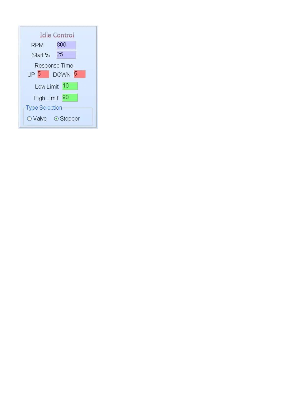
6.7.4.3 Idle Control
Before adjusting the idle control you must select which type of valve is on the engine. Remember if
it is a stepper control (4 to 6 wire), then you require the external electronic driver. Also remember
to set the relevant GP outputs to Idle Control.
Idle control can be used for two-wire and non spring loaded three-wire valves. Other idle valves
with stepper motors will use these settings but with external electronics. Stepper motors will not
use the Low Limit and High Limit settings as they keep their position when there is no signal
present. For two-wire idle valve GP output 2 must be set to Idle Control and for three wire valves
both GP Outputs must be set to Idle Control.
RPM – this setting is the preferred target RPM’s when the engine is on running temperature.
When it is cold the ECU will automatically increase engine RPM’s with up to 300 RPM’s. This is
calculated according to fuel enrichment on the water compensation map.
Start % – this setting is used to increase the air intake when the engine is started hot or cold. The
ECU will open the idle valve with this % and when the engine is cold, the ECU will increase this
setting automatically according to the water temp compensation graph.
Response Time Up – this setting will determine the rate at which the valve opens when the actual
RPM’s fall below the set point in Idle RPM. The further the RPM fall below the set point, the faster
the ECU will open the valve to let in more air. The less the value, the faster the response time will
be. This setting must prevent the engine from stalling when you switch the aircon on or put it in
drive.
Response Time Down – this setting will determine the rate at which the valve closes when the
actual RPM’s go above the set point in Idle RPM. The further the RPM goes above the set point,
the faster the ECU will close the valve to decrease airflow into the engine. This setting is normally
more than the response up to eliminate hunting. The less the value, the faster the response time
will be. This setting must bring over RPM down as fast as possible without hinting the engine.
Low Limit – this setting will preload the spring in the valve so that the valve starts to open
immediately when the ECU starts increasing the value. It can also be used to set minimum idling
RPM for throttle valve that closes completely. To set it start with a larger % and decrease until the
desired idling RPM is reached. When you adjusted the value just accelerate a little so that the
ECU can bring the value from the top.
High Limit – this setting is used to limit the maximum idle RPM’s. No need to open the valve more
than necessary. It also allow for the use of large valves in smaller engines. Just make sure that
when the engine is cold it can lift the RPM up to approx. 1500 RPM. This can be tested by
entering a large Idle RPM value and see to where the ECU can increase the RPM. You need to
lower the RPM first when you changed the value.
Type Selection – this setting is used to select which type of idle control valve is on the engine
because the software is different for the two main types.