21
DE
EN
2.1 SETUP LOCATION
Find a location for the device that meets the following requirements:
• Dry interior
• Device does not cover any ventilation openings.
• Heat-resistant robust base; use floor protection mat if necessary
• Clearance of at least 2 m (6.6 ft) behind the device.
• Clearance of at least 1 m (3.3 ft) on both sides of the device.
• Clearance of at least 30 cm (1.0 ft) in front of the device.
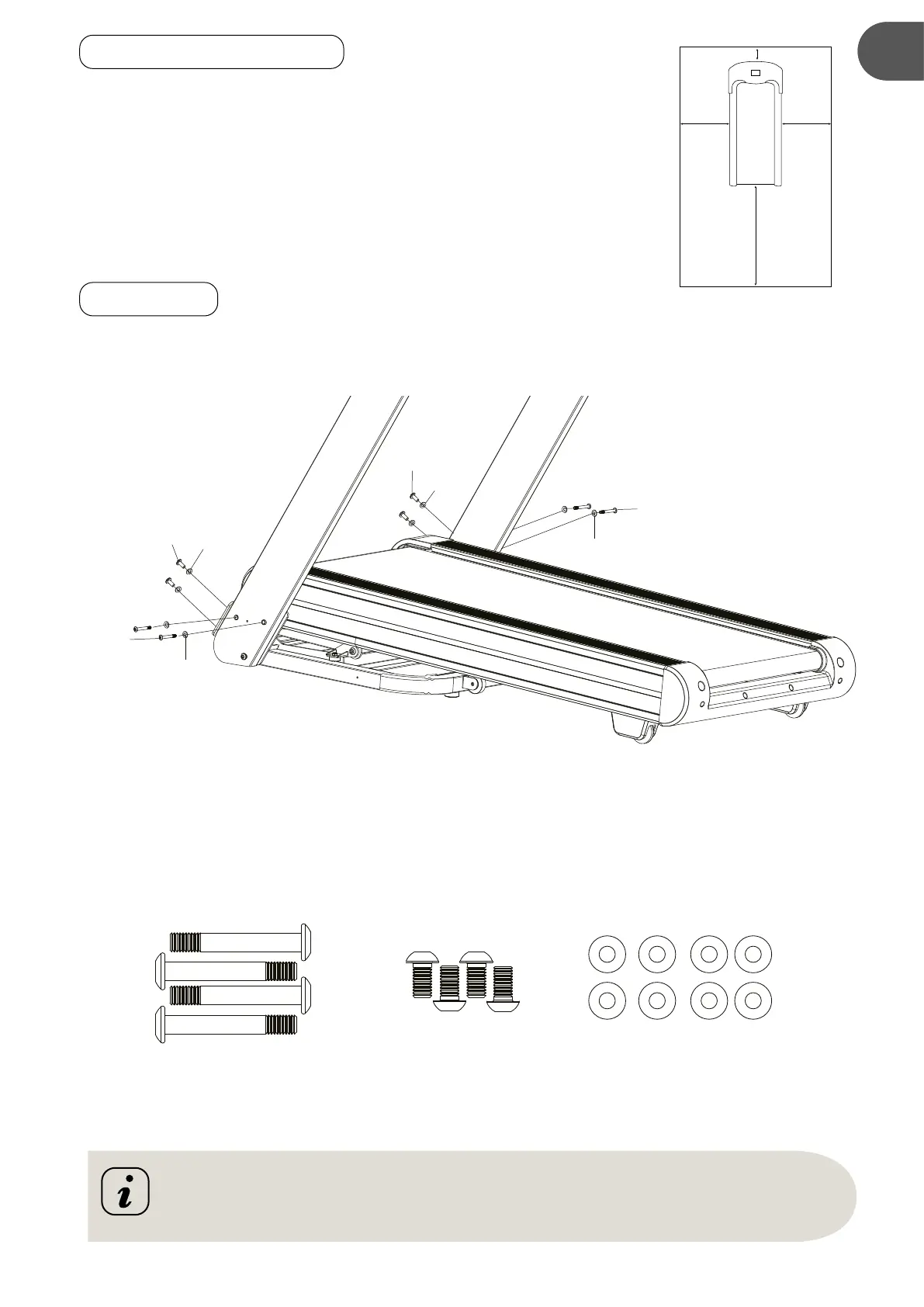
2.2 STEP 1
It is recommended to have a second person assist with this step. Lift the both Right and Left Handlebar
Support Tubes up. One person should hold the both Right and Left Handlebar Support Tubes in place
while the other person tightens the bolts.
• Use four M8×60 Hexagon Socket Oval Head Bolts (S1) and four Washer (S6) to secure both Right and
Left Handlebar Support Tubes onto the Base Frame (A).
• Use four M8×16 Hexagon Socket Oval Head Bolts (S2) and four Washer (S6) to secure both Left/
Right Handlebar Support Tubes onto the Base Frame (A).
2 m
1 m
0,3 m
1 m
(A)
S1
S1
S2
S2
S6
S6
S6
S6
Do not fully tighten bolts in step 1 until step 4 is completed!
M8x60
Hexagon Socket
Oval Head Bolts
Hexagon Socket
Cap Screws
M8x16
Washer
x 8
 Loading...