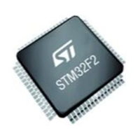
Figure 7. Block diagram for ISO 13849 Cat. 2
I L O
interconnecting means
I input device, e.g. sensor
L logic
O output device, e.g. main contactor
m monitoring
TE test equipment
OTE output of TE
i
m
i
m
OTETE
i
m
m
i
m
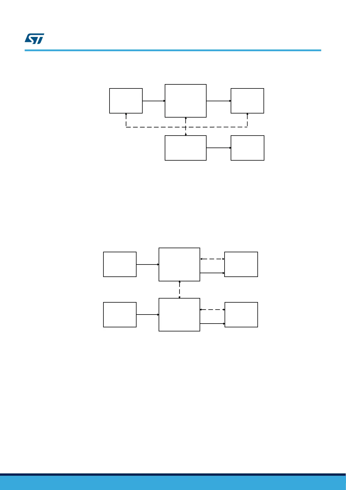
Figure 8. Block diagram for ISO 13849 Cat. 3 and Cat. 4
I1
L1
interconnecting means
c cross monitoring
I1, I2 input device, e.g. sensor
L1, L2 logic
m monitoring
O1, O2 output device, e.g. main contactor
i
m
i
m
O2
L2
c
O1
m
i
m
m
I2
i
m
i
m
A.1.2 ISO 13849 safety metrics computation
Appendix C of ISO 13849 presents tables of standardized MTTFd for the various electric or electronics
components. However, table C.3 in ISO 13849 points to ICs manufacturer’s data while attempting to classify
MTTFd for programmable ICs. As a consequence, safety analysis results of this Safety Manual can be re-mapped
in ISO 13849 domain, because even computed for IEC 61508 they are definitely more and more accurate in the
definition of dangerous failures identification.
When for a certain component PFH << 1 we can assume that MTTFd = 1 / PFH [years].
From the reliability theory, MTTF (the inverse of λ and PFH) is a metric applicable only to not reparable systems.
Nowadays it is a common practice to use MTBF also for not reparable systems where MTBF has to be
UM1845
ISO 13849-1 / ISO 13849-2
UM1845 - Rev 4
page 89/108