UM2324 Rev 4 11/43
UM2324 Hardware layout and configuration
42
6 Hardware layout and configuration
The STM32 Nucleo-64 boards are designed around the STM32 microcontrollers in a 64-pin
LQFP package.
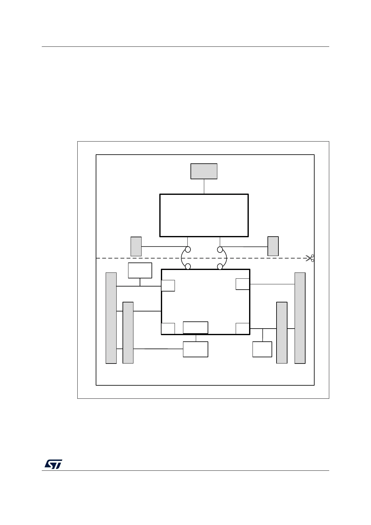
Figure 2 illustrates the connections between the STM32 and its peripherals (STLINK/V2-1,
pushbutton, LED, and morpho connectors).
Figure 3 and Figure 4 help the user to locate these features on the STM32 Nucleo-64 board.
Figure 2. Hardware block diagram
MSv34374V3
Embedded
ST-LINK/V2-1
STM32
microcontroller
RESET
SWD
ST morpho extension header
ST morpho extension header
B2
RESET
B1
USER
ARDUINO
®
connector
LED
LD4
ST-LINK part
MCU part
Mini
USB
UART
IO
IO
IO
IO
ARDUINO
®
connector

 Loading...


