Hardware layout and configuration UM2324
22/43 UM2324 Rev 4
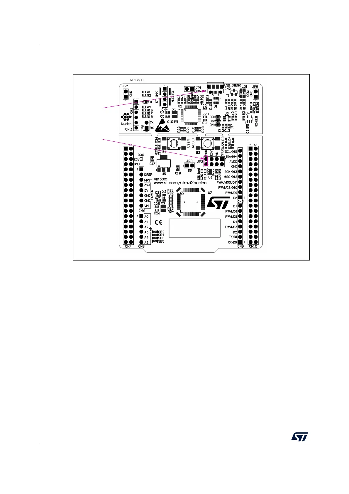
CHG configuration: jumper JP2 [7-8] must be connected as shown in Figure 12.
Figure 12. JP2 [7-8]: CHG power source
6.5.2 External power supply output:
• 5V: The 5V (CN6 pin 5 or CN7 pin 18) is usable as an output power supply for an
ARDUINO
®
shield or an extension board when the STM32 Nucleo-64 board is
powered by USB, VIN, or E5V. In this case, the maximum current allowed is shown in
Table 7.
• 3.3V: on CN6 pin 4 or CN7 pin 16 is usable as power supply output. The current is
limited by the maximum current capability of the regulator U6 (LDL112PV33R from
STMicroelectronics). In this condition, the maximum consumption of the STM32
Nucleo-64 board and the connected shield must be less than 500
mA.
6.6 Programming/debugging when the power supply is not from
ST-LINK
VIN or E5V is usable as an external power supply in case the current consumption of the
STM32 Nucleo-64 board and its extension boards exceed the allowed current on the USB.
In such a condition, it is still possible to use the USB for communication, programming, or
debugging only. In this case, it is mandatory to power the board first using VIN or E5V then
to connect the USB cable to the PC. Proceeding this way the enumeration succeeds, thanks
to the external power source. The following power sequence procedure must be respected:
MSv48506V1
CN2
USB STLK
JP2
PIN 7/8 ON

 Loading...


