Hardware layout and configuration UM2324
26/43 UM2324 Rev 4
6.12 I
DD
measurement
The JP3 labeled-IDD jumper allows the consumption of the STM32 Microcontroller to be
measured by removing the jumper and connecting an ammeter.
• Jumper ON: STM32 Microcontroller is powered (default).
• Jumper OFF: an ammeter must be connected to measure the STM32 microcontroller
current. If there is no ammeter, the STM32 microcontroller is not powered.
6.13 Jumper configuration
The default jumper positions are shown inTable 4. Table 9 describes the other available
jumper settings.
6.14 Configuration of the solder bridges
Table 10 shows the solder bridge configurations and settings.
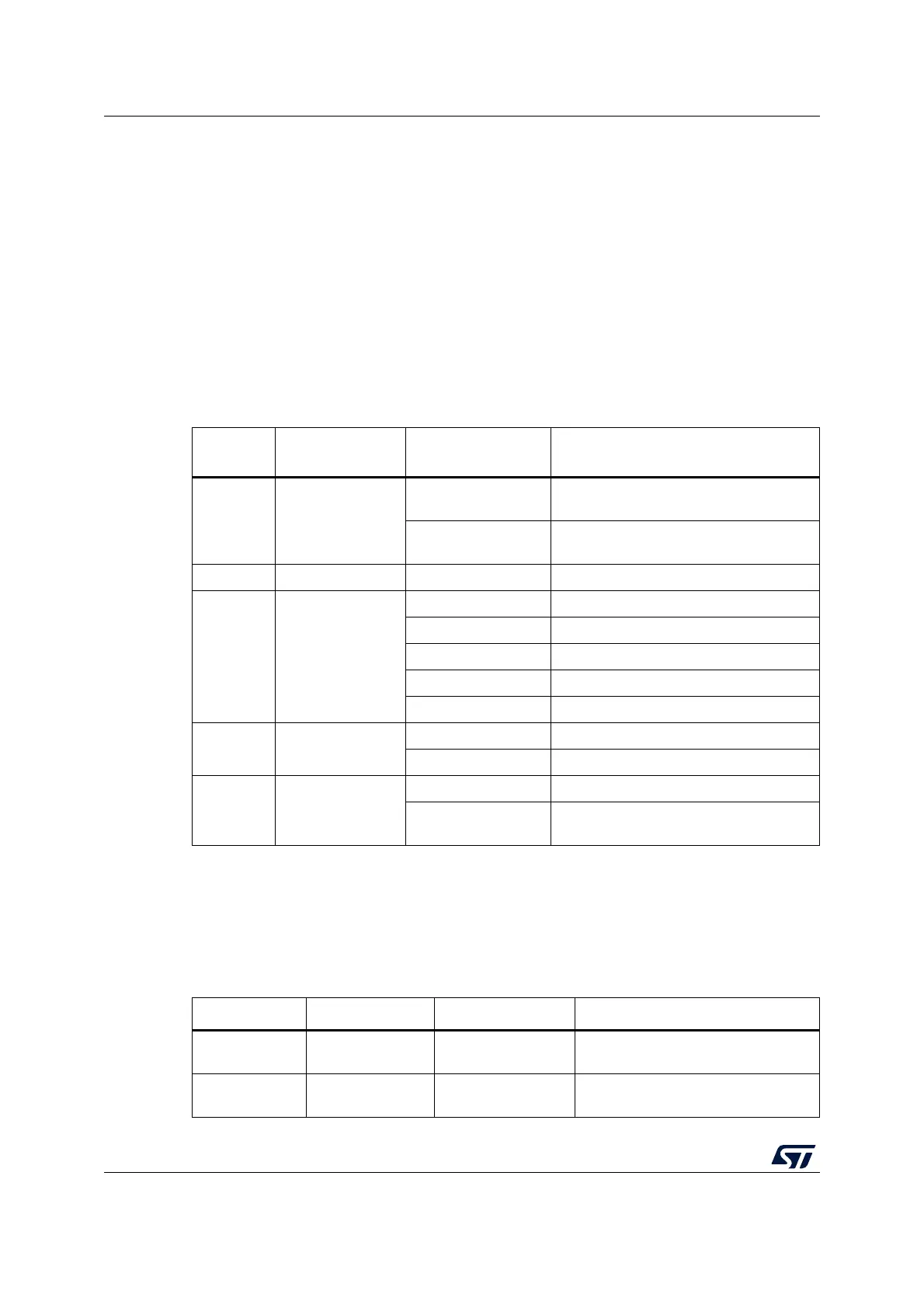
Table 9. Jumper configuration
Jumper /
CN
Function State
(1)
1. Default jumper state is shown in bold.
Comment
CN4
T_SWCLK
T_SWDIO
ON [1-2] ON [3-4]
ST-LINK/V2-1 enable for on-board
MCU debugger
OFF [1-2] OFF [3-4]
ST-LINK/V2-1 functions enabled for
external CN2 connector
JP4/JP5 GND ON GND probe
JP2
5 V Power
selection
ON [1-2] 5 V from ST-LINK
ON [3-4] 5 V from VIN 7 V to 12 V
ON [5-6] 5 V from E5V
ON [7-8] 5 V from USB_CHG
OFF No 5 V power
JP1 STLK Reset
ON [1-2] STLK Reset
OFF No STLK Reset
JP3 I
DD
measurement
ON [1-2] VDD = 3.3 V
OFF
To connect the external source
(ULPBench probe as an example)
Table 10. Solder bridge configurations and settings
Definition Bridge State
(1)
Comment
SWD interface
(default))
SB7/SB9
/SB11/SB13
ON Reserved, do not modify.
SWD interface
(reserved)
SB6/SB8
/SB10/SB12
OFF Reserved, do not modify.

 Loading...


