UM2324 Rev 4 21/43
UM2324 Hardware layout and configuration
42
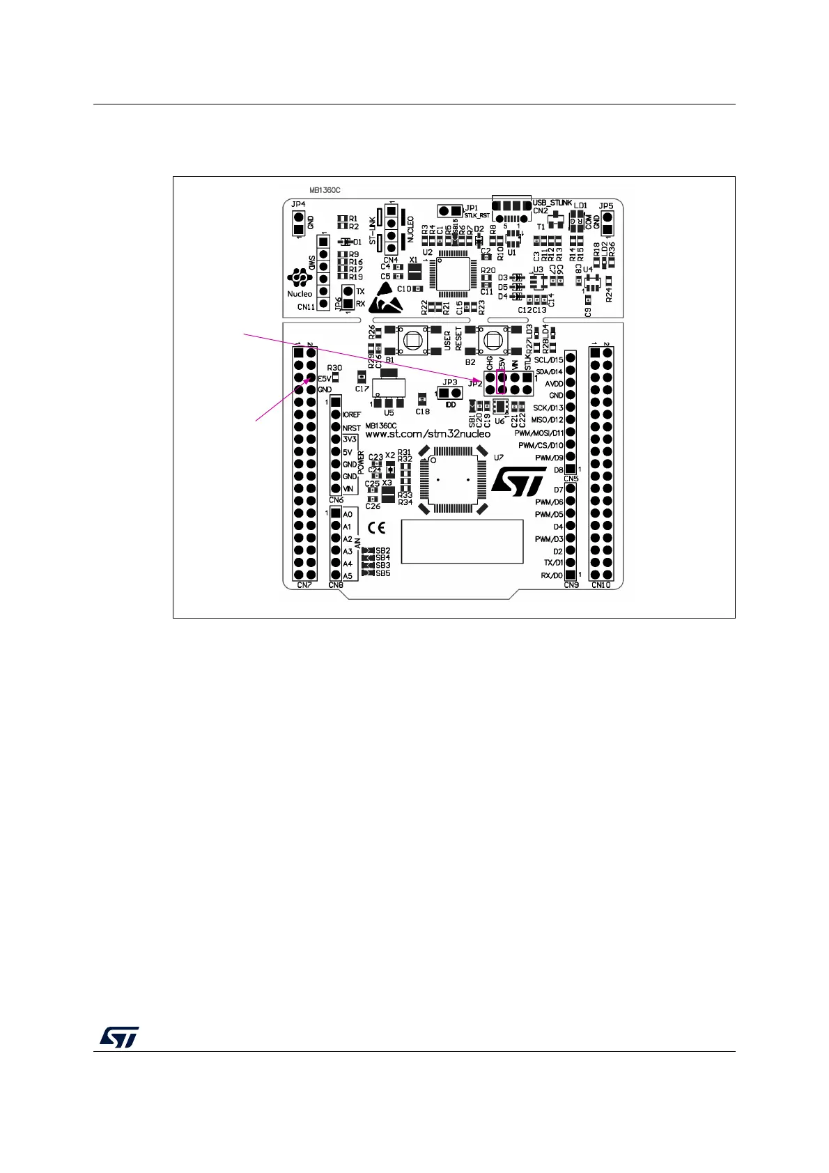
E5V configuration: Jumper JP2 [5-6] must be connected as shown in Figure 11.
Figure 11. JP2 [5-6]: STLK power source
5V_USB_CHARGER is the DC power charger connected to USB ST-LINK (CN2). To select
the CHG power source on the JP2 silkscreen, the JP2 jumper must be on pins 7 and 8. In
this case, if the STM32 Nucleo-64 board is powered by an external USB charger the debug
is not available. If the PC is connected instead of the charger, the limitation is no more
effective and the PC can be damaged.
MSv48505V1
E5V: CN7 PIN6
JP2
PIN 5/6 ON

 Loading...


