EasyManuals Logo

ST STM32G070RBT6 User Manual

ST STM32G070RBT6
44 pages
To Next Page IconTo Next Page
To Previous Page IconTo Previous Page
Page #20 background imageLoading...
Page #20 background image
Hardware layout and configuration UM2324
20/43 UM2324 Rev 4
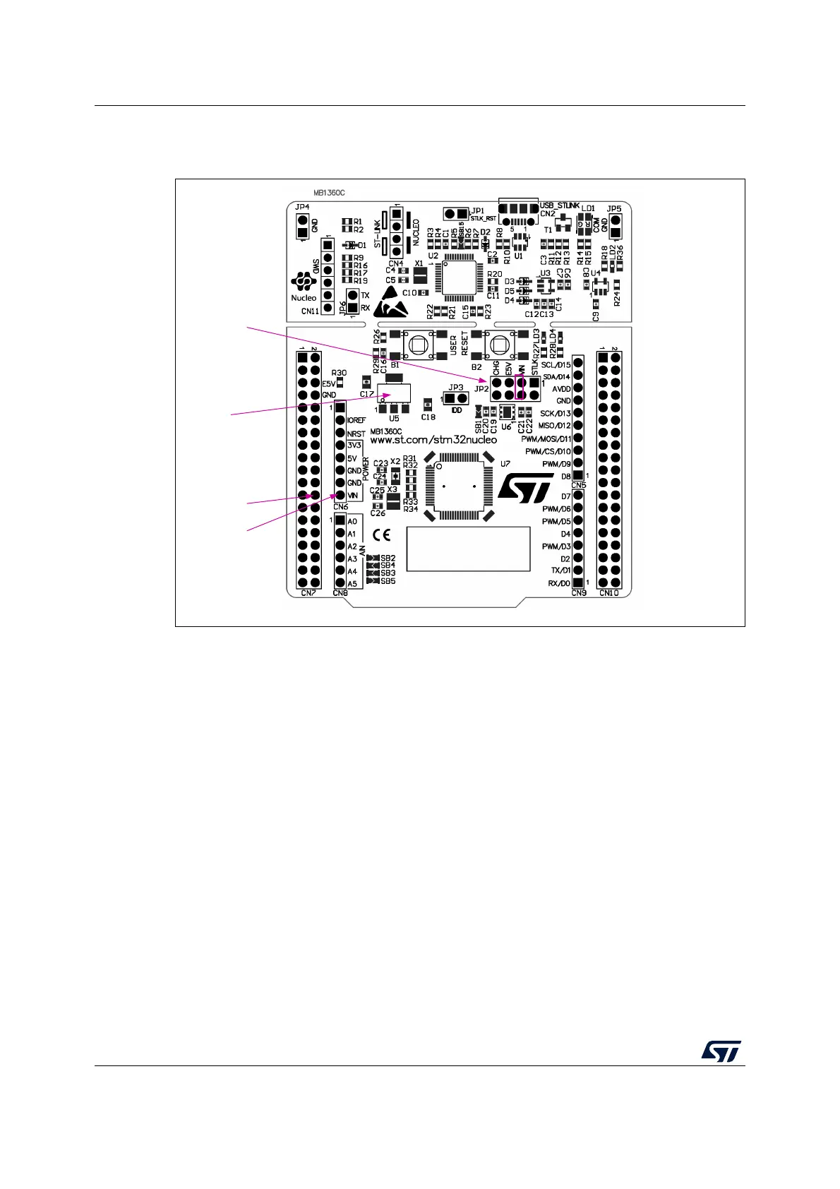
VIN configuration: jumper JP2 [3-4] must be connected as shown in Figure 10.
Figure 10. JP2 [3-4]: STLK power source
E5V is the DC power coming from external (5V DC power from pin 6 of the CN7 ST morpho
connector). In this case, the JP2 jumper must be on pins 5 and 6 to select the E5V power
source on the JP2 silkscreen.
MSv48504V1
U5
VIN 7-12V
VOUT 5V
JP2
PIN 3/4 ON
CN7 PIN24
CN6 PIN8

Table of Contents

Questions and Answers:

Question and Answer IconNeed help?

Do you have a question about the ST STM32G070RBT6 and is the answer not in the manual?

ST STM32G070RBT6 Specifications

General IconGeneral
BrandST
ModelSTM32G070RBT6
CategoryMotherboard
LanguageEnglish

Related product manuals