Connectors UM2324
30/43 UM2324 Rev 4
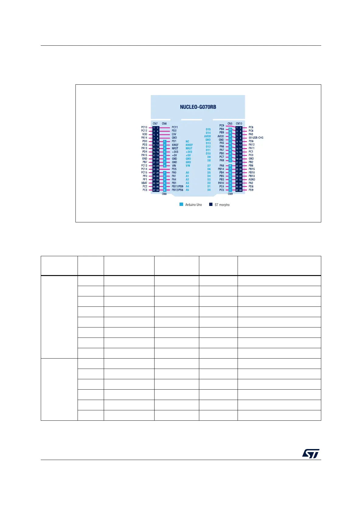
The related pinout for the ARDUINO
®
connector is shown in Figure 15 and Figure Note: and
listed in Table 12.
Figure 15. STM32 Nucleo-64 boards ARDUINO
®
connector pinout
Note: ARDUINO
®
Uno V3 D0 and D1 signals are connected by default on USART1 (MCU I/O PC4
and PC5).
Table 12. ARDUINO
®
connector pinout
Connector
Pin
number
Pin
name
Signal name STM32 pin Function
CN6
1 NC - - Reserved for test
2 IOREF - - I/O reference
3 NRST NRST NRST RESET
4 3V3 - - 3.3 V input/output
5 5V - - 5 V output
6GND - - GND
7GND - - GND
8 VIN - - 7 V to 12 V power input
CN8
1 A0 ADC PA0 ARD_A0_IN0
2 A1 ADC PA1 ARD_A1_IN1
3 A2 ADC PA4 ARD_A2_IN4
4 A3 ADC PB1 ARD_A3_IN9
5 A4 ADC PB9 or PB11 ARD_A4_IN15|| I2C_1_SCL
6 A5 ADC PB8 or PB12 ARD_A5_IN16|| I2C_1_SDA

 Loading...


