7.5 Reset sources
The general reset of the STM32H7B3I-DK Discovery kit is active LOW. Sources of reset are:
• RESET button B1
• Embedded STLINK-V3E
• ARDUINO
®
Uno shield board through CN19 connector, pin 3
• MIPI10 and TAG connectors (Reset from the debugging tool)
The general reset is connected to the following peripheral reset functions:
• STM32H7B3LIH6Q MCU reset
• Octo-SPI Flash reset
• Camera reset
• LCD reset
•
Wi‑Fi
®
module reset (optional)
7.6 Board functions
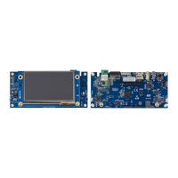
7.6.1 TFT color LCD 480x272 pixels
The STM32H7B3I-DK board includes a 4.3-inch LCD touchscreen board which is connected to the RGB interface
of the STM32H7B3LIH6Q through the CN1 50-pin connector. The MB1315 LCD board uses the RK043FN48H-
CT672B TFT LCD from Rocktech with a driving system, a white LED backlight, and a capacitive touch panel. The
touchscreen controller interfaces with the STM32H7B3LIH6Q via the bidirectional I2C4 bus, since the TFT LCD
reset is controlled by the NRST general reset. A U14 external SDRAM is also used to store display data.
7.6.2 USB OTG HS
The STM32H7B3I-DK board supports USB OTG high-speed communication via a CN15 USB Micro-AB connector
and a U20 Hi-Speed USB 2.0 external PHY. A U25 USB power switch is also connected to V
BUS
and provides
power to CN15. The green LED LD6 is lit in one of these cases:
• The power switch is ON and the STM32H7B3I-DK board works as a USB host
• V
BUS
is powered by another USB host when the STM32H7B3I-DK board works as a USB device.
The red LED LD8 is lit when an overcurrent occurs (Higher than 500 mA).
Note: The STM32H7B3I-DK board can be powered by the CN15 USB connector at 5 V DC with a 500 mA current
limitation.
7.6.3 EXT_I2C
An EXT_I2C connector socket is available on the STM32H7B3I-DK board and offers the possibility to connect
external modules via the I2C4 bus. The EXT_RESET is managed by an I/O signal from the STM32H7B3LIH6Q
MCU.
7.6.4
microSD
™
card
A CN4 slot for microSD
™
card (SD 2.0 compliant) is available on the STM32H7B3I-DK board and is connected
to the SDIO1 interface of the STM32H7B3LIH6Q. The microSD
™
card detection is managed by the uSD_Detect
signal. When a microSD
™
card is inserted in the slot, the uSD_Detect signal level is LOW, otherwise, it is HIGH.
Limitations:
On the STM32H7B3I-DK board, some SDIO1 signals are shared with some digital camera interface DCMI
signals. As a consequence, the user must pay attention that there is no camera connected to CN7 when using the
microSD
™
card.
UM2569
Reset sources
UM2569 - Rev 6
page 19/53
 Loading...


