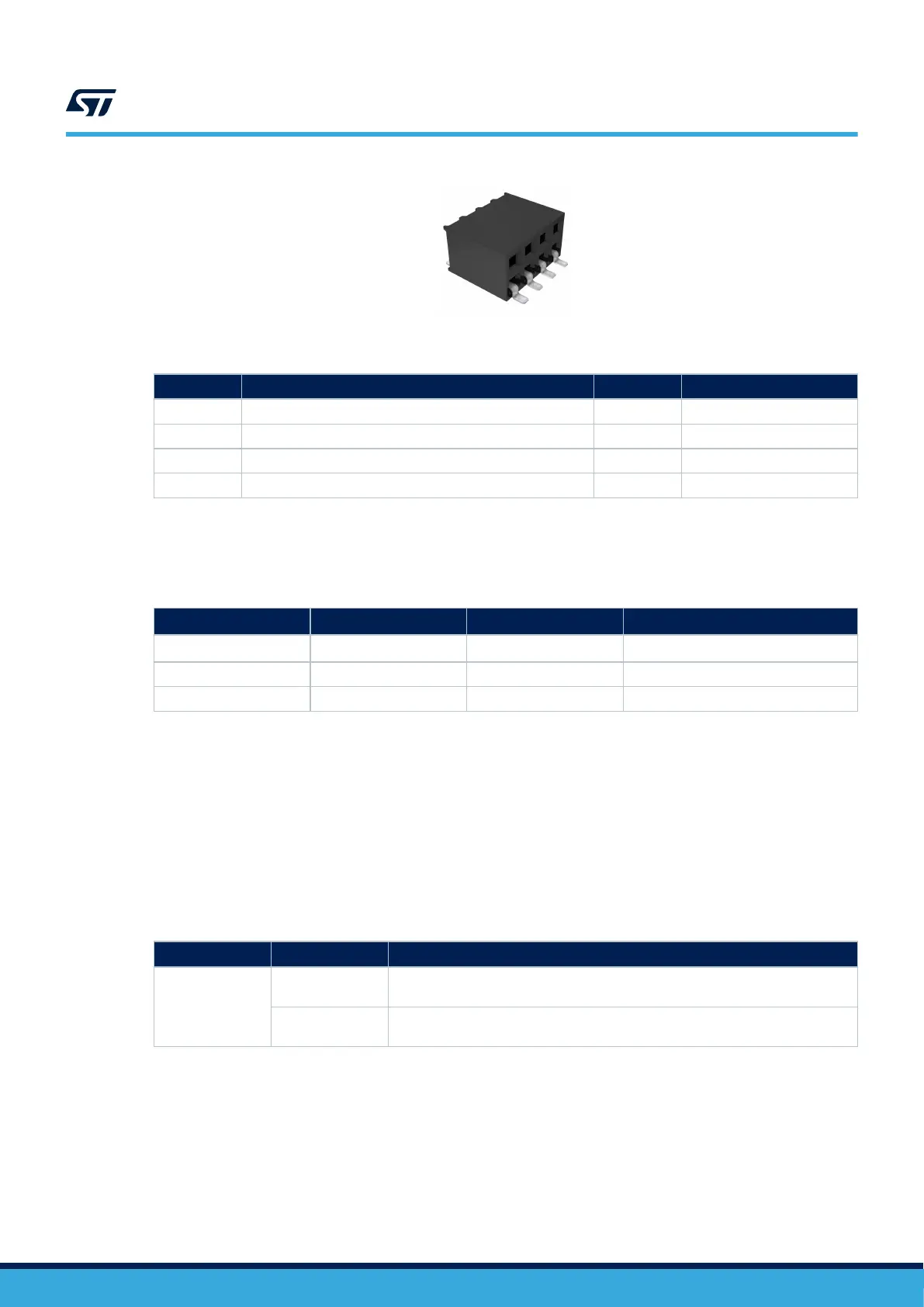
Figure 22. CN16 EXT_I2C connector
Table 18. CN16 EXT_I2C connector pinout
Pin number Description Pin number Description
1 NC 5 EXT_RESET ( PB6)
2 GND 6 I2C4_SCL (PD12)
3 NC 7 NC
4 VDD (3V3) 8 I2C4_SDA (PD13)
As I2C4 is available for external use, it is important to note those following I2C4 addresses are already used
onboard:
Table 19. I2C4 onboard addresses
Application
W/R I
2
C address I
2
C maximum speed
Comment
TFT LCD touch panel 0x71 and 0x70 400 kHz
Default I
2
C address
Audio codec 0x95 and 0x94 100 kHz -
Camera 0x61 and 0x60 400 kHz For STM32F4DIS-CAM module
8.8 CN3 audio connector
The 2x10-male-pin 1.27 mm-pitch audio connector is used for the audio MEMS daughter extension using the
DFSDM interface. The reference to be used is the MB1299 MEMS microphone daughterboard. The MB1299
embeds five digital MEMS microphones.
Limitations:
On the STM32H7B3I-DK board, some DFSDM signals are shared with STMod+ signals. As a consequence, the
user must make sure that nothing is connected to the P1 STMod+ connector (Pins 17 and 19).
Table 20. DFSDM – Solder bridge configuration
Solder bridge
Setting
(1)
Configuration
SB48, SB50
SB48, SB50 ON
DFSDM1_2_DATIN1 and DFSDM1_2_CKOUT are connected to PB12 and PB0
of STM32H7B3LIH6Q MCU.
SB48, SB50 OFF
DFSDM interface not connected: DFSDM1_2_DATIN1 and DFSDM1_2_CKOUT
are not connected to PB12 and PB0 of STM32H7B3LIH6Q MCU.
1. The default configuration is shown in bold.
UM2569
CN3 audio connector
UM2569 - Rev 6
page 30/53
 Loading...


