8.4 P1 STMod+ connector
The standard 20-pin STMod+ connector is available on the STM32H7B3I-DK board to increase compatibility
with external boards and modules from the Ecosystem of microcontrollers. By default, it is designed to support
an ST‑dedicated fanout board to connect different modules or board extensions from different manufacturers.
The fanout board also embeds a 3.3 V regulator and I
2
C level shifters. For more detailed information on the
fanout board, refer to the user manual STMod+ fan-out expansion board for STM32 Discovery kits and Evaluation
boards (UM2695).
For details about the STMod+ interface, refer to the technical note STMod+ interface specification (TN1238).
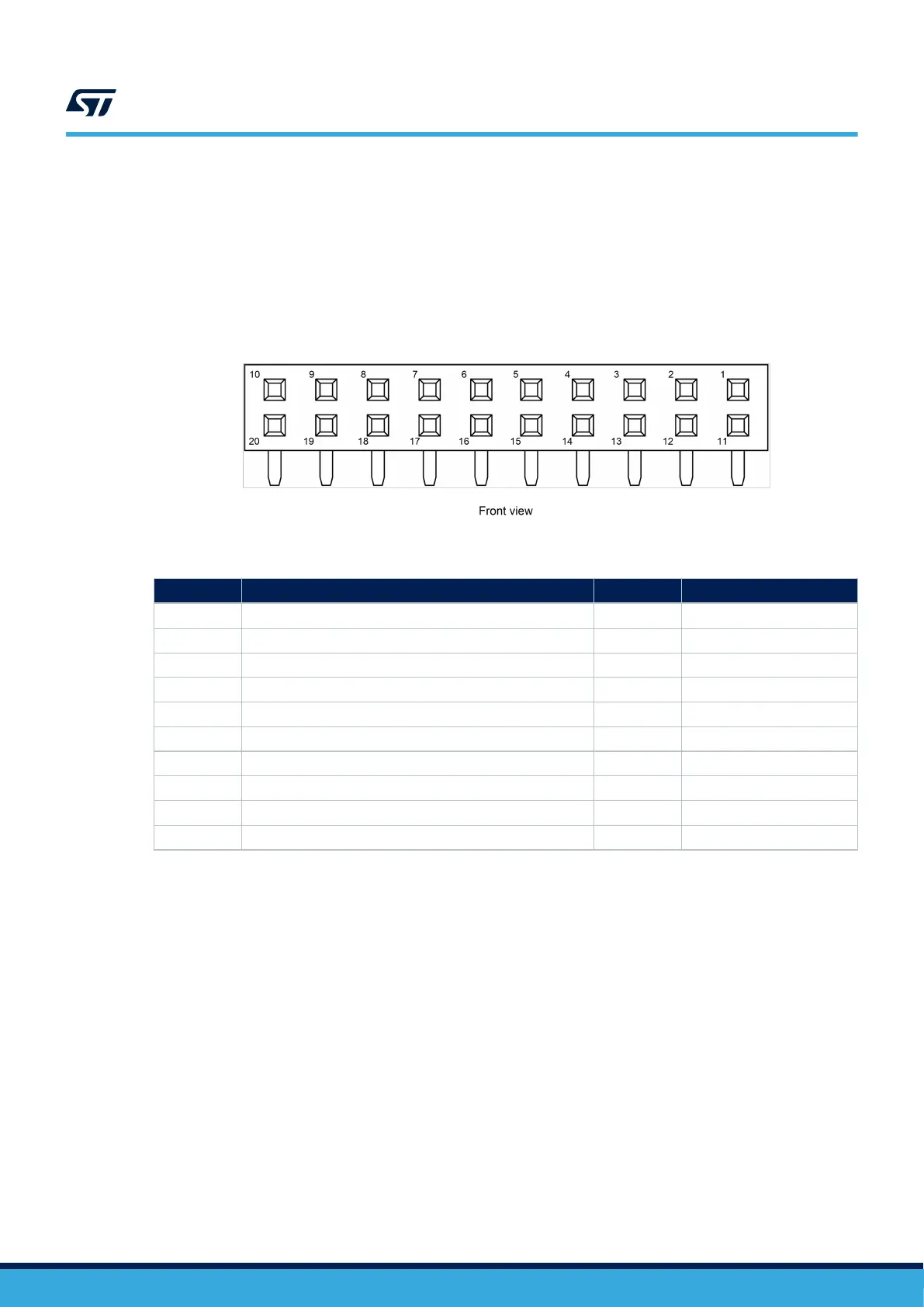
Figure 19. P1 STMod+ connector
Table 15. P1 STMod+ connector pinout
Pin number Description Pin number Description
1 SPI2_NSS / USART2_CTS (PA11/PA0) 11 INT (PC6)
2 SPI2_MOSI / USART2_TX (PC3/PD5) 12 RESET (PH8)
3 SPI2_MISO / USART2_RX (PC2/PD6) 13 ADC (PA4)
4 SPI2_SCK / USART2_RTS (PA12/PD4) 14 PWM (PF8)
5 GND 15 5V
6 5V 16 GND
7 I2C4_SCL (PD12) 17 DFSDM-DATA3 (PC7)
8 SPI2_MOSIs (PB15) 18 DFSDM-CKOUT (PD3)
9 SPI2_MISOs (PB14) 19 DFSDM-DATA7 (PB9)
10 I2C4_SDA (PD13) 20 DFSDM-CK7 (PB8)
Note: This connector shares many GPIOs with other functions on the boards. For more detailed information, refer to
Section Appendix A STM32H7B3I-DK I/O assignment. Also, to have a quick look at STMod+ GPIO sharing and
multiplexing, and to get a quick view of other alternate functions available on its pins, refer to Section Appendix
B STMod+ GPIO sharing and multiplexing.
UM2569
P1 STMod+ connector
UM2569 - Rev 6
page 27/53

 Loading...


