AN3216 Power supplies
Doc ID 17496 Rev 5 11/30
2.3.1 Power-on reset (POR)/power-down reset (PDR),
brownout reset (BOR)
The monitoring voltage begins at 0.7 V.
During power-on, for devices operating between 1.8 and 3.6 V, the BOR keeps the device
under reset until the supply voltages (V
DD
and V
DDIO
) come close to the lowest acceptable
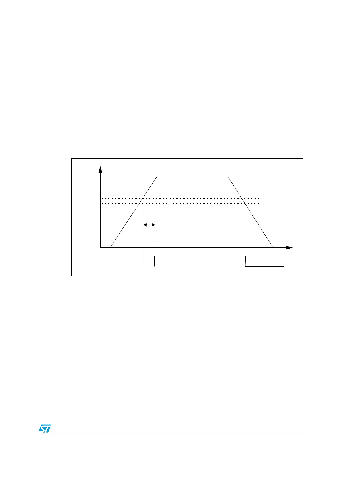
voltage (1.8 V). At power-up this internal reset is maintained during ~1 ms to wait for the
supply to reach its final value and stabilize.
At power-down the reset is activated as soon as the power drops below the lowest limit
(1.65 V).
At power-on, a defined reset should be maintained below 0.7 V. The upper threshold for a
reset release is defined in the electrical characteristics section of the product datasheets.
Figure 4. Power on reset/power down reset waveform
If you want to run the cpu at full speed the threshold should be raised to 2.0 V. For a
programmable threshold above the chip lowest limit, a brownout reset can be configured to
the desired value. The BOR can also be used to detect a power voltage drop earlier. The
threshold values of the BOR can be configured through the FLASH_OBR option byte.
2.3.2 Programmable voltage detector (PVD)
The device features an embedded programmable voltage detector (PVD) that monitors the
V
DD
/V
DDA
power supply and compares it to the V
PVD
threshold. Seven different PVD levels
can be selected by software between 1.85 V and 3.05 V, with a 200 mV step. An interrupt
can be generated when V
DD
/V
DDA
drops below the V
PVD
threshold and/or when V
DD
/V
DDA
is higher than the V
PVD
threshold. The interrupt service routine then generates a warning
message and/or puts the MCU into a safe state. The PVD is enabled by software
configuration. As an example, the service routine can perform emergency shutdown tasks.
V
DD
/V
DDA
Reset
POR
PDR
Temporization
t
RSTTEMPO