AN3216 Power supplies
Doc ID 17496 Rev 5 9/30
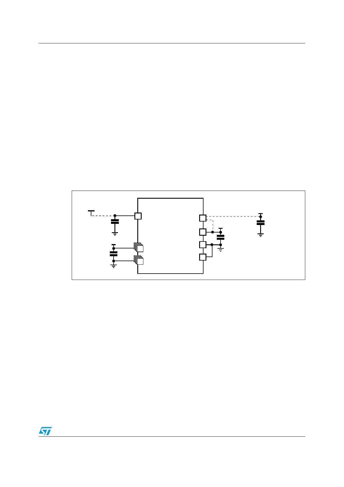
2.2 Power supply schemes
The circuit is powered by a stabilized power supply, V
DD
.
● The V
DD
pins must be connected to V
DD
with external decoupling capacitors; one
single Tantalum or Ceramic capacitor (minimum 4.7 µF typical 10 µF) for the package +
one 100 nF Ceramic capacitor for each V
DD
pin).
● The V
DDA
pin must be connected to two external decoupling capacitors (100 nF
Ceramic capacitor + 1 µF Tantalum or Ceramic capacitor).
● The V
REF+
pin can be connected to the V
DDA
external power supply. If a separate,
external reference voltage is applied on V
REF+
, a 100 nF and a 1 µF capacitor must be
connected on this pin. To compensate peak consumption on Vref, the 1 µF capacitor
may be increased up to 10µF when the sampling speed is low. When ADC or DAC is
used, VREF+ must remain between 1.8 V and VDDA. VREF+ can be grounded when
ADC and DAC are not active; this enables the user to power down an external voltage
reference.
● Additional precautions can be taken to filter analog noise: V
DDA
can be connected to
V
DD
through a ferrite bead.
Figure 2.
Power supply scheme
1. Optional. If a separate, external reference voltage is connected on V
REF+
, the two capacitors (100 nF and
1 µF) must be connected.
2. V
REF
+ is either connected to V
DDA
or to V
REF
.
3. N is the number of V
DD
and V
SS
inputs.
2.3 Reset and power supply supervisor
The input supply to the main and low power regulators is monitored by a power-on/power-
down/brownout reset circuit. Power-on/power-down reset are a null power monitoring with
fixed threshold voltages, whereas brownout reset gives the choice between several
thresholds with a very low, but not null, power consumption.
In addition, the STM32L1xxx embeds a programmable voltage detector that compares the
power supply with the programmable threshold. An interrupt can be generated when the
power supply drops below the V
PVD
threshold and/or when the power supply is higher than
the V
PVD
threshold. The interrupt service routine then generates a warning message and/or
puts the MCU into a safe state.
6
,#$
34-,XXX
.§N&
6
$$
§&
N&&
N&&
NOTE
6
,#$
6
2%&
6
$$!
6
33!
6
2%&n
6
$$.
6
33.
6
2%&
6
$$
AID
&
OPTIONAL