Reference design AN3216
26/30 Doc ID 17496 Rev 5
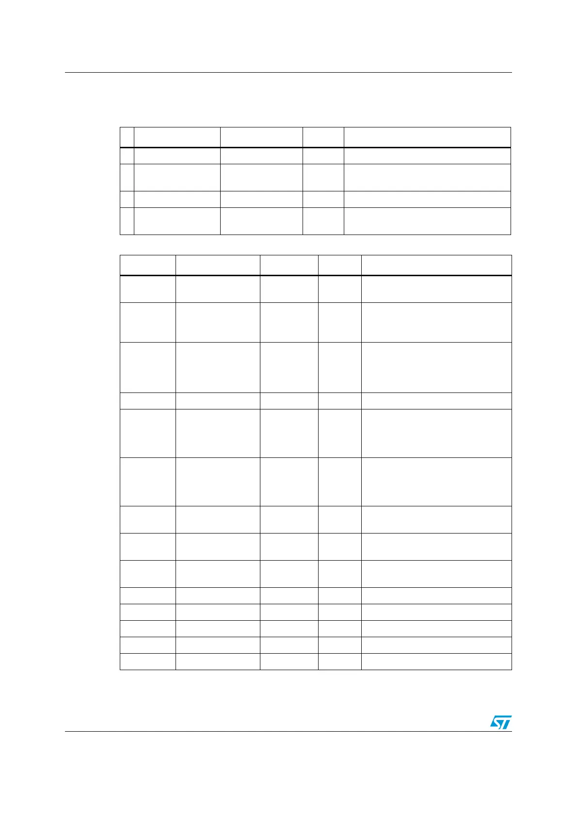
7.2 Component references
Table 4. Mandatory components
Id Components name Reference Quantity Comments
1 Microcontroller STM32L152VB(T6) 1 100-pin package
2 Capacitors 100 nF 3 ... 6
Ceramic capacitors (decoupling
capacitors)
3 Capacitor 10 µF 1 Ceramic capacitor (decoupling capacitor)
4 Capacitor 1 µF 2
Ceramic capacitor (LCD booster or
decoupling capacitor)
Table 5. Optional components
Id Components name Reference Quantity Comments
R2, R4, R5,
R7, R8
Resistor 10 kΩ 9
Pull-up and pull-down for JTAG and
Boot mode.
R6 Resistor 0 Ω 1
Used for HSE: the value depends on
the crystal characteristics.
A typical value is 390 Ω.
R1 Resistor 0 Ω 2
Used for LSE: the value depends on
the crystal characteristics.
This resistor value is given only as a
typical example.
R3 Resistor 0 Ω 1 For low pass filter
C3, C5,
C10, C11,
C12, C13,
C14, C15
Capacitor 100 nF 8 Ceramic capacitor
C1, C2 Capacitor 6.8 pF 2
Used for LSE: the value depends on
the crystal characteristics. Fits for
MC-306 32.768K-E3, which has a
load capacitance of 6 pF.
C7, C8 Capacitor 20 pF 2
Used for HSE: the value depends on
the crystal characteristics.
C4, C6 Capacitor 1 µF 2
Ceramic capacitors (decoupling
capacitors)
C9 Capacitor 10 µF 1
Ceramic capacitors (decoupling
capacitors)
X2 Quartz 8 MHz 1 Used for HSE
X1 Quartz 32 kHz 1 Used for LSE
CN1 JTAG connector HE10 1
SW1, SW2 Switch 3V3 2 Used to select the right boot mode
B1 Push-button B1 1