AN3216 Clocks
Doc ID 17496 Rev 5 15/30
3.2 HSE OSC clock
The high-speed external clock signal (HSE) can be generated from two possible clock
sources:
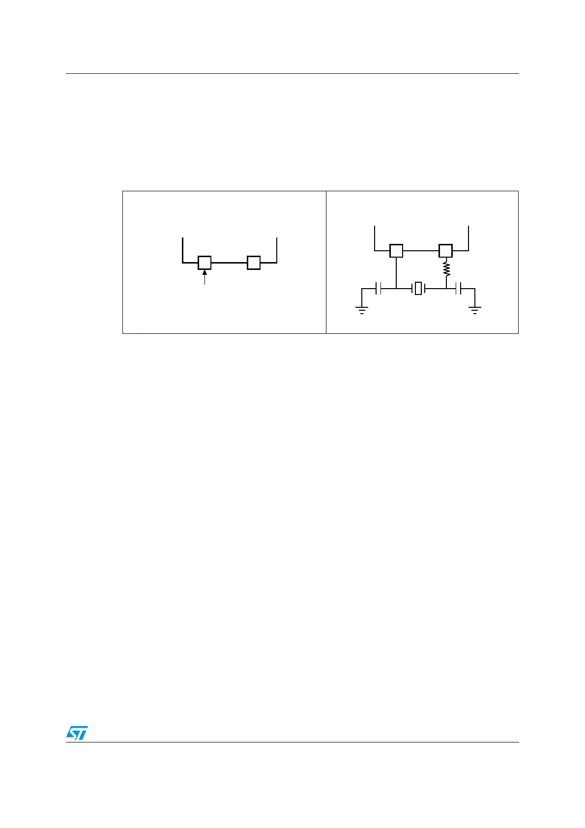
● HSE user external clock (see Figure 7)
● HSE external crystal/ceramic resonator (see Figure 8)
1. The value of R
EXT
depends on the crystal characteristics. A typical value is in the range of 5 to 6 R
S
(resonator series resistance).
2. Load capacitance, C
L
, has the following formula: C
L
= C
L1
x C
L2
/ (C
L1
+ C
L2
) + C
stray
where: C
stray
is the
pin capacitance and board or trace PCB-related capacitance. Typically, it is between 2 pF and 7 pF. Please
refer to Section 6: Recommendations on page 23 to minimize its value.
3.2.1 External source (HSE bypass)
In this mode, an external clock source must be provided. It can have a frequency of up to
32 MHz.
The external clock signal (square, sine or triangle) with a duty cycle of about 50%, has to
drive the OSC_IN pin while the OSC_OUT pin must be left in the high impedance state (see
Figure 7 and Figure 8).
3.2.2 External crystal/ceramic resonator (HSE crystal)
The external oscillator frequency ranges from 1 to 24 MHz.
The external oscillator has the advantage of producing a very accurate rate on the main
clock. The associated hardware configuration is shown in Figure 8.
The resonator and the load capacitors have to be connected as close as possible to the
oscillator pins in order to minimize output distortion and startup stabilization time. The load
capacitance values must be adjusted according to the selected oscillator.
For C
L1
and C
L2
it is recommended to use high-quality ceramic capacitors in the 5 pF to 25
pF range (typical), designed for high-frequency applications and selected to meet the
requirements of the crystal or resonator. C
L1
and C
L2,
are usually the same value. The
crystal manufacturer typically specifies a load capacitance that is the series combination of
C
L1
and C
L2
. The PCB and MCU pin capacitances must be included when sizing C
L1
and
C
L2
(10 pF can be used as a rough estimate of the combined pin and board capacitance).
Refer to the electrical characteristics sections in the datasheet of your product for more
details.
Figure 7. External clock Figure 8. Crystal/ceramic resonators
OSC_OUTOSC_IN
External source
(Hi-Z)
ai14369
Hardware configuration
/3#?/54/3#?).
AIB
34-,XXX
2
%84
#
,
#
,
(ARDWARECONFIGURATION