7.11.2 Operating voltage
All LEDs are driven by the I/O level; they are operating in the 3.3 V voltage range.
7.11.3 LED interface
Table 11 describes the I/O configuration of the LED interface.
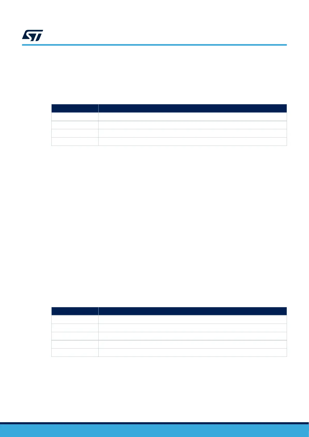
Table 11. I/O configuration of the LED interfaces
I/O Configuration
PA14 PA14 is connected to the blue LED LD3. Active Low.
PA13 PA13 is connected to the red LED LD4. Active Low.
MCP IO14 MCP IO14 is connected to the green LED LD7. Active High.
MCP IO15 MCP IO15 is connected to the orange LED LD6. Active High.
7.12 Buttons
7.12.1 Description
The STM32MP135F-DK Discovery kit provides five buttons:
• USER1 button (B1)
– Used at boot time by U-Boot to enter the USB programming mode
• USER2 button (B2)
– Used at boot time by U-Boot to enter the Android
™
Fastboot mode
• Wake-up button (B3)
– Allows the platform to be woken up from any low-power mode
– Connected to STPMIC1 PONKEY, which generates a wake-up signal on STM32MP135FAF7 pin PF8
• Tamper button (B4)
– Allows the detection of case opening as a security event
• Reset button (B5)
– Used to reset the Discovery kit
7.12.2 I/O interface
Table 12 describes the I/O configuration for the physical user interface.
Table 12. I/O configuration for the physical user interface
I/O
Configuration
PA14 USER1 button (B1)
PA13 USER2 button (B2)
- Wake-up button (B3). Connected to the PONKEY pin of the STPMIC1
PA6 Tamper button (B4)
NRST Reset button (B5). Active Low.
UM2993
Buttons
UM2993 - Rev 2
page 18/42