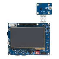
7.13 CSI-DCMI
7.13.1 Description
The STM32MP135F-DK Discovery kit provides an external camera module with a 1/4" color CMOS UXGA
2-megapixel image sensor. A CSI-DCMI bridge deserializes data from the camera module, which are then
transmitted to the MPU.
The resolution is up to 1600 x 1200 with 20 frames per second.
Output signals are 8-bit RGB RAW.
The control signals are I2C5.
7.13.2 DCMI I/O interface
Table 13 describes the I/O configuration for the DCMI interface.
Table 13. I/O configuration for the DCMI interface
I/O Configuration
PA9 PA9 is connected to DCMI_D0
PD0 PD0 is connected to DCMI_D1
PG10 PG10 is connected to DCMI_D2
PE4 PE4 is connected to DCMI_D3
PD11 PD11 is connected to DCMI_D4
PD3 PD3 is connected to DCMI_D5
PB8 PB8 is connected to DCMI_D6
PE14 PE14 is connected to DCMI_D7
PB7 PB7 is connected to DCMI_PIXCLK
PG9 PG9 is connected to DCMI_VSYNC
PH8 PH8 is connected to DCMI_HSYNC
MCP_IO1 MCP_IO1 is connected to STMIPI_ERROR
MCP_IO0 MCP_IO0 is connected to STMIPI_INT
PD7 PD7 is connected to STMIPI_EXTCLK
MCP_IO2 MCP_IO2 is connected to STMIPI_XSDN
PD1 PD1 is used as I2C5_SCL shared between USB and touch panel
PH6 PH6 is used as I2C5_SDA shared between USB and touch panel
UM2993
CSI-DCMI
UM2993 - Rev 2
page 19/42

 Loading...