7.6 Reset sources
The reset signal of STM32MP135F-DK is active low. The internal PU forces the RST signal to a high level.
The sources of reset are:
• Reset button B5 (black button)
• STPMIC1
• Embedded STLINK-V3
• STM32MP135F-DK
7.7 Boot mode
7.7.1 Description
At startup, the boot pins select the boot source used by the internal boot ROM. Table 4 describes the
configurations of the boot pins.
Table 4. Boot mode pins
Boot 0 Boot 1 Boot 2 Boot mode
0 0 0 Forced USB boot for programming.
0 0 1 Reserved.
1 0 1
SD
™
card on SDMMC1.
Other combinations Not supported.
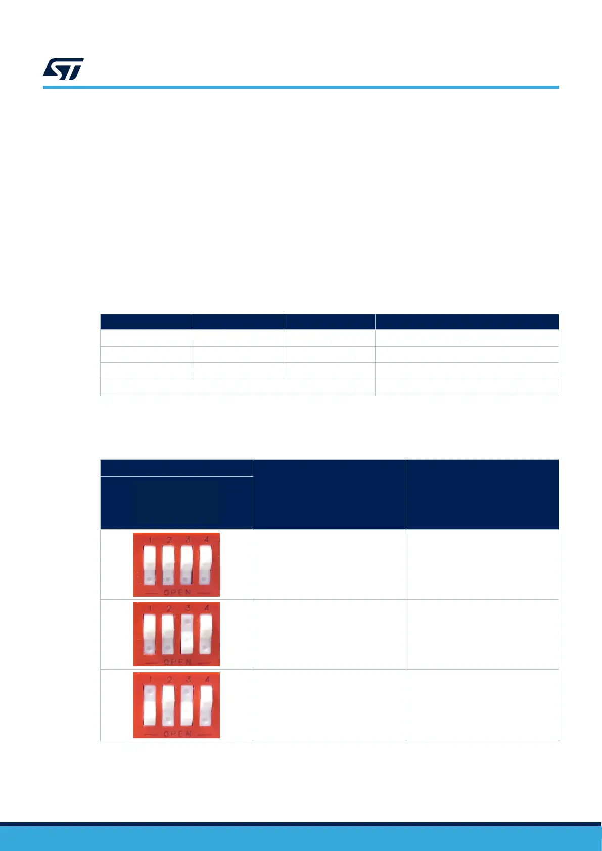
Table 5 shows the configurations of the boot mode switch SW1.
Table 5. Boot mode switch SW1
Switch positions
(1)
Boot pin selection Boot mode
Boot0
Boot1
Boot2
NC
Boot0: 0
Boot1: 0
Boot2: 0
NC: X
(2)
Forced USB boot for programming.
Boot0: 0
Boot1: 0
Boot2: 1
NC: X
(2)
Reserved.
Boot0: 1
Boot1: 0
Boot2: 1
NC: X
(2)
SD
™
card on SDMMC1.
1. Not connected.
2. X is either 1 or 0.
UM2993
Reset sources
UM2993 - Rev 2
page 13/42