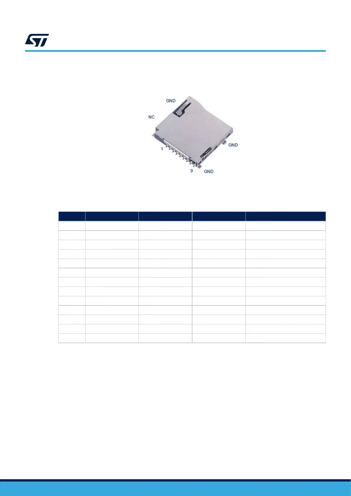
Figure 8 shows the pinout of the microSD
™
card connector CN3.
Figure 8. microSD
™
card connector CN3
Table 10 describes the pinout of the microSD
™
card connector CN3.
Table 10. CN3 microSD
™
card connector pinout
Pin Pin name Signal name STM32 pin Function
1 DAT2 SDMMC1_D2 PC10 SDIO.D2
2 DAT3_CD SDMMC1_D3 PC11 SDIO.D3
3 CMD SDMMC1_CMD PD2 SDIO.CMD
4 VDD VDD_SD - VDD_SDCARD
5 CLK SDMMC1_CLK PC12 SDIO.CLK
6 VSS GND - GND
7 DAT0 SDMMC1_D0 PC8 SDIO.D0
8 DAT1 SDMMC_D1 PC9 SDIO.D1
9 CARD_DETECT μSD_DETECT PH4 μSD_DETECT active low
10 GND GND - GND
11 GND GND - GND
12 GND GND - GND
13 NC NC NC NC
7.11 LEDs
7.11.1 Description
The LD1 LED turns green when the power cable is inserted in connector CN12.
Two general-purpose LED color LEDs (LD3 and LD6) are available as light indicators:
• The LD3 blue LED is used as Linux
®
Heartbeat LED, which is blinking as long as Linux
®
is alive on the
Cortex
®
-A.
• The LD6 orange LED is used as STM32Cube examples verdict LED.
The two indicator LEDs, the red LD4 and green LD7 LEDs, are respectively connected to the STM32MP135 MPU
and to the MCP series I/O expander.
UM2993
LEDs
UM2993 - Rev 2
page 17/42