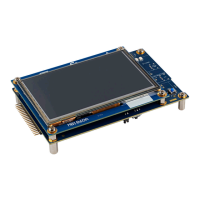
6.4 Embedded STLINK-V3EC
The chapter below gives some information about the implementation of the STLINK-V3EC on this board.
For detailed information about the STLINK-V3EC capabilities such as LED management, drivers, and firmware,
refer to the technical note Overview of ST-LINK derivatives (TN1235).
For information about the debugging and programming features of the STLINK-V3EC, refer to the user manual
STLINK-V3SET debugger/programmer for STM8 and STM32 (UM2448).
Figure 8. STM32U5G9J-DK2 ST-LINK
DT59221V1
STLK_NRST
header (JP3)
STLINK_V3EC
(U13)
STLINK USB
(CN8)
MIPI10 connector
(CN11)
Tag-Connect™
footprint (CN10)
ST-LINK
COM LED (LD7)
ST-LINK
power LED (LD6)
6.4.1 Description
There are two different ways to program and debug the onboard STM32 MCU:
• Using the embedded STLINK-V3EC
• Using an external debug tool connected to the MIPI10 connector (CN11) or the Tag‑Connect
™
footprint
(CN10) with a TC2050-IDC-NL cable
Features supported in STLINK-V3EC:
• 5 V/500 mA power supplied by the USB Type-C
®
connector (CN1)
• USB 2.0 USB high-speed‑compatible interface
• JTAG and Serial Wire Debug (SWD) with Serial Wire Viewer (SWV)
• Virtual COM port (VCP)
• COM status LED (LD7), which blinks during communication with the PC
• Power status LED (LD6), which gives information about STLINK-V3EC target power
• USB-C
®
overvoltage protection (U16) with current limitation
For detailed information about these LEDs, refer to the technical note Overview of ST-LINK derivatives (TN1235).
UM3223
Hardware layout and configuration
UM3223 - Rev 1
page 10/37

 Loading...