List of figures
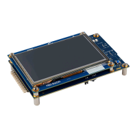
Figure 1. STM32U5G9J-DK2 with LCD (top view)...................................................1
Figure 2. STM32U5G9J-DK2 without LCD (top view) ................................................1
Figure 3. STM32U5G9J-DK2 (bottom view) .......................................................1
Figure 4. STM32U5G9J-DK2 hardware block diagram ...............................................7
Figure 5. Main board layout (top view)...........................................................8
Figure 6. Main board layout (bottom view) ........................................................8
Figure 7. Main board mechanical drawing (in millimeters) .............................................9
Figure 8. STM32U5G9J-DK2 ST-LINK ......................................................... 10
Figure 9. STM32U5G9J-DK2 power diagram .....................................................13
Figure 10. 5 V power source selection .......................................................... 13
Figure 11. STLK (CN8) selection for 5 V power ....................................................14
Figure 12.
ARDUINO
®
(CN5) selection for 5 V power ................................................ 15
Figure 13. Application USB (CN2) selection for 5 V power ............................................. 15
Figure 14. Current consumption measurement jumper (JP4) ........................................... 16
Figure 15. Boot mode selection switch (SW1) ..................................................... 17
Figure 16.
USB Type-C
®
connector pinout (CN4) ...................................................18
Figure 17.
STM32U5G9J-DK2 ARDUINO
®
connectors ...............................................22
Figure 18. General extension connector (CN1)..................................................... 24
UM3223
List of figures
UM3223 - Rev 1
page 36/37

 Loading...