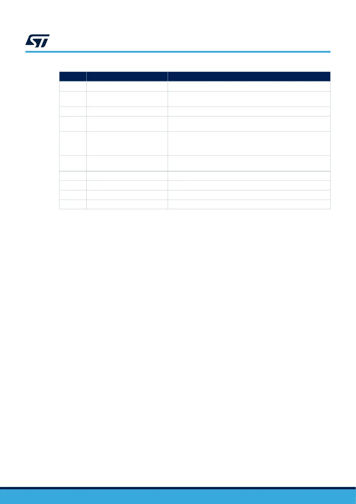
Table 6. Tag‑Connect
™
footprint (CN10) pinout for TC2050-IDC-NL cable
CN10 pin Signal Function
1 VDD
Target VDD (indication to the probe)
(2)
2 JTMS_SWDIO
Target SWDIO using SWD protocol or target JTMS (T_JTMS) using JTAG
protocol
3 GND Ground
4 JTCK_SWCLK
Target SWCLK using SWD protocol or target JTCK (T_JTCK) using JTAG
protocol
5 GND
Ground
It must be disconnected (SB13) if the debugger probe provides a power
supply on this pin
6 JTDO_SWO
Target SWO using SWD protocol or target JTDO (T_JTDO) using JTAG
protocol (SB44 ON)
(3)
7 NC NC
8 JTDI Not used by SWD protocol, target JTDI (T_JTDI) using JTAG protocol
9 JNRST JNRST using JTAG protocol
10 NRST Target reset
1. Not connected on this board
2. Output for this board
3. SWO is optional and required only for Serial Wire Viewer (SWV) trace.
4. NC means not required for the SWD connection, or not connected on this board
5. Tied to GND. The external debugger might use it.
6. Input for this board
UM3223
Hardware layout and configuration
UM3223 - Rev 1
page 12/37

 Loading...


