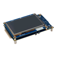
7.4 Buttons and LEDs
Two buttons are available on STM32U5G9J-DK2.
• Side reset button:
– B1 is connected to the global reset signal (NRST of STM32U5G9ZJT6Q MCU).
• Blue user button:
– B2 is connected to PC13-WKUP2.
– When the button is pressed, the logic state is HIGH, otherwise, the logic state is LOW.
Six LEDs are available on STM32U5G9J-DK2.
• STLINK-V3EC LEDs:
– LD6 provides information about the STLINK-V3EC power status.
– LD7 provides information about the STLINK-V3EC communication status.
– For more detailed information about these two LEDs, refer to the STLINK-V3EC technical note
(TN1235).
• User LEDs:
– LD2 is a red LED connected to PD2.
– LD3 is a green LED connected to PD4.
• 5 V PWR LED:
– LD1 is a green LED indicating 5 V power.
• USB LED:
– LD5 is a green LED indicating a USB Host connection.
UM3223
Board functions
UM3223 - Rev 1
page 20/37

 Loading...