Controller Connections
Instruction Manual
123
Part No. 19-pin 24V I/O Port Included
21C104800 Mating Connector - Solder pins Standard
21C104802 Mating Connector - Crimp pins Optional
21C104804 Mating Connector - Crimp pins, crimp tool Optional
21E102202 Breakout Box for plinth mounting Optional
21C202005 I/O Cable 5M Optional
21C202010 I/O Cable 10M Optional
21C202020 I/O Cable 20M Optional
21C2020XX schematic
When the Alpha controller is used with fixtured tools, it must use a Remote Start/Stop/Reverse pendent to the
controller to provide basic switching control for the tool.
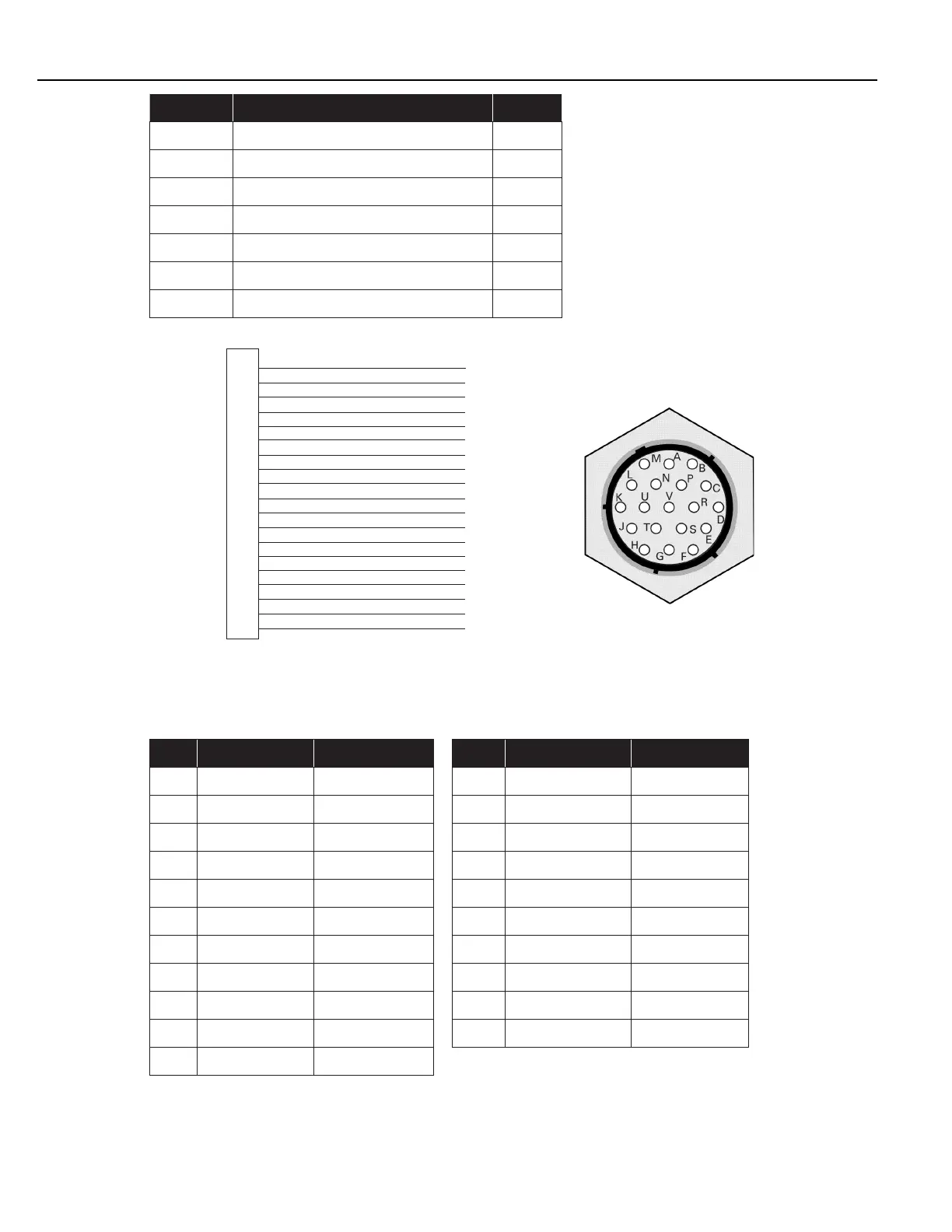
Pin descriptions are shown in the following table:
Pin # Description PLC Address Pin # Description PLC Address
C Output O:0.0/0 L Input I:0.0/0
D Output O:0.0/1 M Input I:0.0/1
E Output O:0.0/2 N Input I:0.0/2
F Output O:0.0/3 P Input I:0.0/3
G Output O:0.0/4 R Input I:0.0/4
H Output O:0.0/5 S Input I:0.0/5
J Output O:0.0/6 T Input I:0.0/6
K Output O:0.0/7 U Input I:0.0/7
A 24 VDC N/A V 24 VDC Return N/A
B Output Supply N/A
Schematics of the Inputs, Outputs and other pins, with cabling, are shown below: