MODBUS TCP
QB Expert Alpha Controller
148
6.13.1 Example Map
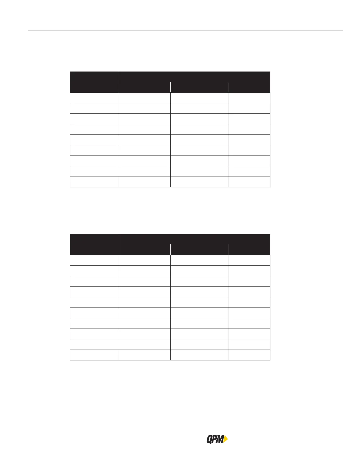
Here is an example of mapping addresses between an external PLC and the Alpha controller after the I/O functions
have been assigned in the Alpha controller.
Controller Inputs
External PLC Alpha Controller
Address
#
Modbus Input* Assigned Function Length (Bits)
30001:0
0/0 Start
1
30001:1
0/1 Stop
1
30001:2
0/2 Reverse
1
30001:3
0/3 Job Select (Bit) 0
1
30001:4
0/4 Job Select (Bit) 1
1
30001:5
0/5 Job Select (Bit) 2
1
30001:6, 7
0/6 Ignored
2
30001:8 - 15
1/0 Ignored
8
30002
2/0 Part ID (ASCII)
80
#
Register:Bit
*Byte/Bit
Integer, Float and ASCII data must start on a zero (first) bit of a byte and not in the middle of a byte. Function
code 03 (0x03) can only transmit a 16-bit register, not the individual bits within a register. The PLC will need to
send the 16-bit register and the Alpha controller will parse the individual bits after receipt.
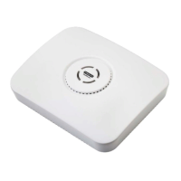
Controller Outputs
External PLC Alpha Controller
Address
#
Modbus Output* Assigned Function Length (Bits)
40001:0
0/0 Fault
1
40001:1
0/1 Ready
1
40001:2
0/2 Tool Running
1
40001:3
0/3 In Cycle
1
40001:4
0/4 Cycle OK
1
40001:5
0/5 Cycle NOK
1
40001:6, 7
0/6 Not Used
2
40001:8 -15
1/0 Not Used
8
40002
2/0 Torque (Float)
32
40004 6/0 Angle (Float)
32
#
Register:Bit *Byte/Bit
Integer, Float and ASCII data must start on a zero (first) bit of a byte and not in the middle of a byte. Function
code 04 (0x04) can only transmit a 16-bit register, not the individual bits within a register. The PLC will need to
capture the 16-bit register and then parse the individual bits after receipt.