Do you have a question about the Star Micronics BSC10 Series and is the answer not in the manual?
Check all necessary accessories are included in the package after unpacking the unit.
Guidelines for choosing a suitable environment and location for printer installation.
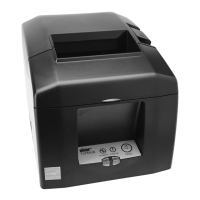
Identifies key external parts of the printer, including covers, control panel, and buttons.
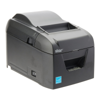
Details the various ports and controls located on the printer's exterior for connectivity and operation.
Instructions for connecting the printer to a PC via USB, Parallel, RS-232C, and Ethernet cables.
Procedures for connecting various interface cables, including USB and Parallel, to the printer.
Details connecting RS-232C and Ethernet cables to the printer and network setup.
Explanation of the Ethernet interface's link disconnection detection and recovery features.
Configuration options for Ethernet functions using dip switches on the printer.
Step-by-step guide on connecting the AC adapter for power supply and recommended power specifications.
Procedures for turning the printer on and connecting peripheral devices like cash drawers.
Instructions on how to properly load a paper roll into the printer.
Details the required specifications for paper thickness, width, and dimensions for optimal performance.
Guide on adjusting the paper roll guide to accommodate different paper widths.
Important safety warnings and cautions to follow during the printer setup process.
Explanation of POWER and ERROR lamp states for identifying recoverable and unrecoverable printer errors.
Tips and procedures to avoid paper jams during normal printer operation.
Step-by-step guide on how to safely clear jammed paper from the printer.
Procedure to release the auto cutter if it becomes locked during operation or paper jams.
Instructions for cleaning the thermal print head to maintain print quality and prevent damage.
Guide on cleaning the rubber roller to remove dirt and ensure proper paper feeding.
Steps for cleaning the paper holder to remove dust and debris.
Instructions for cleaning sensors to ensure accurate paper detection.
The BSC10 Series Thermal Printer is a robust and versatile device designed for efficient and reliable printing in various commercial environments. This hardware manual provides comprehensive instructions for unpacking, installation, setup, operation, and maintenance, ensuring users can maximize the printer's performance and longevity.
The BSC10 Series Thermal Printer is primarily used for printing receipts, tickets, and other transactional documents. It operates using thermal printing technology, which means it does not require ink or toner, relying instead on heat to produce images on special thermal paper. This makes it a cost-effective and low-maintenance solution for businesses.
The printer is equipped with a control panel that features a FEED button, a POWER lamp (green), and an ERROR lamp (red). The FEED button allows for manual paper feeding when the printer is online, facilitating quick adjustments or paper advancement. The POWER lamp indicates when the printer is online and ready for operation, while the ERROR lamp signals various operational issues or errors, often in combination with the POWER lamp.
Connectivity options vary depending on the model. The BSC10UC/BSC10UD models typically offer an interface connector for connecting to a host PC via a cable and a USB port for USB cable connections. Both models also include a power inlet for an optional AC adapter and a peripheral drive connector for connecting devices such as cash drawers. It is crucial to note that the peripheral drive connector should not be connected to a telephone line to prevent malfunction.
The BSC10LAN model, designed for network environments, features a 100/10BASE Ethernet connector, allowing it to connect to various host computers via an Ethernet cable. This model also includes dip switches for setting Ethernet functions, such as DHCP address acquisition timeout and network settings reset. A unique feature of the Ethernet interface model is its link disconnection detection, where the POWER and ERROR lamps flash simultaneously to indicate a disconnected Ethernet cable or an unrecognized IP address.
The printer is designed to handle different paper widths, specifically 79.5 ± 0.5 mm and 57.5 ± 0.5 mm, with a maximum roll diameter of 102 mm. This flexibility allows users to adapt the printer to various printing needs. The paper roll guide can be adjusted to accommodate the desired paper width, a process that should be performed carefully and only when the printer is not in use to prevent wear and tear on internal components.
Setting up the BSC10 Series printer involves several key steps to ensure proper functionality. First, the printer should be placed on a firm, level surface, away from direct sunlight, heaters, and sources of extreme heat or humidity. It should also be connected to a reliable power outlet that is not shared with appliances causing power spikes.
Connecting the interface cable to the PC depends on the model and the available ports. For USB models, a USB cable connects to the PC's USB port. Parallel models use a parallel cable connected to the PC's parallel port, while RS-232C models require an RS-232C cable. For Ethernet models, the Ethernet cable connects to the PC's Ethernet port or a router/hub. Before connecting or disconnecting any interface cable, it is essential to disconnect the AC adapter's power cord from the outlet. Once connected, cables should be routed through the provided cable hooks to secure them in place.
Connecting the AC adapter is a critical step. Users must ensure the printer and all connected devices are turned off and the power cord is removed from the outlet before connecting the AC adapter to the printer and then plugging the power cable into an AC outlet. It is recommended to use the standard AC adapter and power cord. If using an optional power supply, it must meet specific voltage and current capacity requirements (24 VDC ± 10% and 2.1 A or more) and support SELV output, while also considering noise protection and static electricity measures.
Turning on the printer is straightforward: after connecting the power cord, the power switch on the left side of the printer is flipped, and the POWER lamp on the control panel should light up.
Loading a paper roll involves opening the rear cover by placing fingers in the grooves on either side of the printer. The paper roll is then loaded in the specified direction, and the leading edge is pulled straight out. It is crucial to pull the paper straight and not at an angle to prevent jams. After loading, the rear cover is closed by pushing on both sides, ensuring it is securely shut. The printer will perform initial operations, including paper feeding and cutting, during which the cover should not be opened.
Changing the paper width requires adjusting the paper roll guide. The guide is removed, then reinserted into the appropriate groove for the desired paper width (e.g., 58 mm or 80 mm). This adjustment should only be done when the printer is off, and the printer utility's memory switch setting should be updated to match the new paper width.
The printer also features a peripheral drive connector for devices like cash drawers. Connecting a modular jack plug from the peripheral device to this connector allows for integrated system functionality. Again, caution is advised against connecting telephone lines to this port.
Regular maintenance is essential to ensure the BSC10 Series printer operates efficiently and to prevent issues such as unprinted characters due to paper dust accumulation. As a guideline, maintenance should be performed every six months or every 1 million lines of printing. Crucially, the printer's power switch must be turned off before any maintenance is performed.
The thermal print head is a sensitive component that requires careful cleaning. Blackened paper dust can accumulate on its surface, affecting print quality. To clean it, a cotton swab or soft cloth dipped in alcohol (ethanol, methanol, or isopropyl) should be used to gently wipe the surface. Users must avoid touching the thermal head immediately after printing when it is hot, and care must be taken to prevent static electricity discharge, which can damage the head's driver IC and other components. Metal objects or abrasive materials like sandpaper should never be used on the thermal head.
The platen rubber roller, which helps feed the paper, can accumulate dirt. It should be cleaned with a dry, soft cloth, rotating the roller to clean its entire surface.
The paper holder should also be cleaned of any debris, dust, or paper particles that may accumulate over time.
Sensors and their surrounding areas are vital for proper printer operation, especially reflection sensors. If these become dirty, detection may not be performed correctly. Cleaning these areas with a brush or similar tool can help maintain their functionality.
In cases of paper jams, the first step is to turn off the power switch. The rear cover is then opened, and the jammed paper is carefully removed. If the rear cover cannot be opened, the cutter lock may need to be manually released. This involves removing the front cover, removing any visible jammed paper, and then turning a knob in front of the cutter in the direction of the red arrow until the rear cover can be opened. After clearing the jam, the paper roll is reloaded straight, the rear cover is securely closed, and the front cover is reattached before turning the power switch back on. It is important to ensure the ERROR lamp is not lit, indicating that the printer is ready to accept commands.
The manual also emphasizes several cautions:
These detailed instructions and warnings ensure that users can effectively maintain their BSC10 Series Thermal Printer, prolonging its operational life and ensuring consistent, high-quality performance.
| Print Resolution | 203 dpi |
|---|---|
| Compatible Paper | Thermal paper roll |
| Print Method | Thermal |
| Connectivity | Bluetooth, USB |
| Battery Life | Up to 8 hours |