Notice
If in the country setting Italy is set, then the
RS485 bus must be connected as follows to
enable control through an external device in
accordance with CEI 0-21.
– External fast switch-off (ital.: Teledistacco):
If the lines 3
1)
and 8
1)
of the RS485 bus
2)
are
connected, e. g. via an external relay, the
following applies:
Relay closes: The inverters on the bus dis-
connect themselves from the network.
Relay opens: The inverters connected on
the network connect themselves to the net-
work (regular operation).
– Switch-over of the grid frequency discon-
nection thresholds (Ital.: Modalità definitiva
di funzionamento del sistema di protezione
di interfaccia (impiego del SPI sulla base di
letture locali e di informazioni/comandi
esterni)): If the lines 5
1)
and 8
1)
of the
RS485 bus
2)
are connected, e. g. via an
external relay, the following applies:
Relay closes: The inverters connected on
the bus set the switch-off thresholds in
accordance with CEI 0-21 to 47.5 Hz and
51.5 Hz.
Relay opens: The inverters connected on
the bus set the switch-off thresholds in
accordance with the country setting Italy ;
Ä
Chapter 8 „Technical data“ on page 57.
We recommend that you integrate the wiring of
lines 3, 5, and 8 in the bus termination.
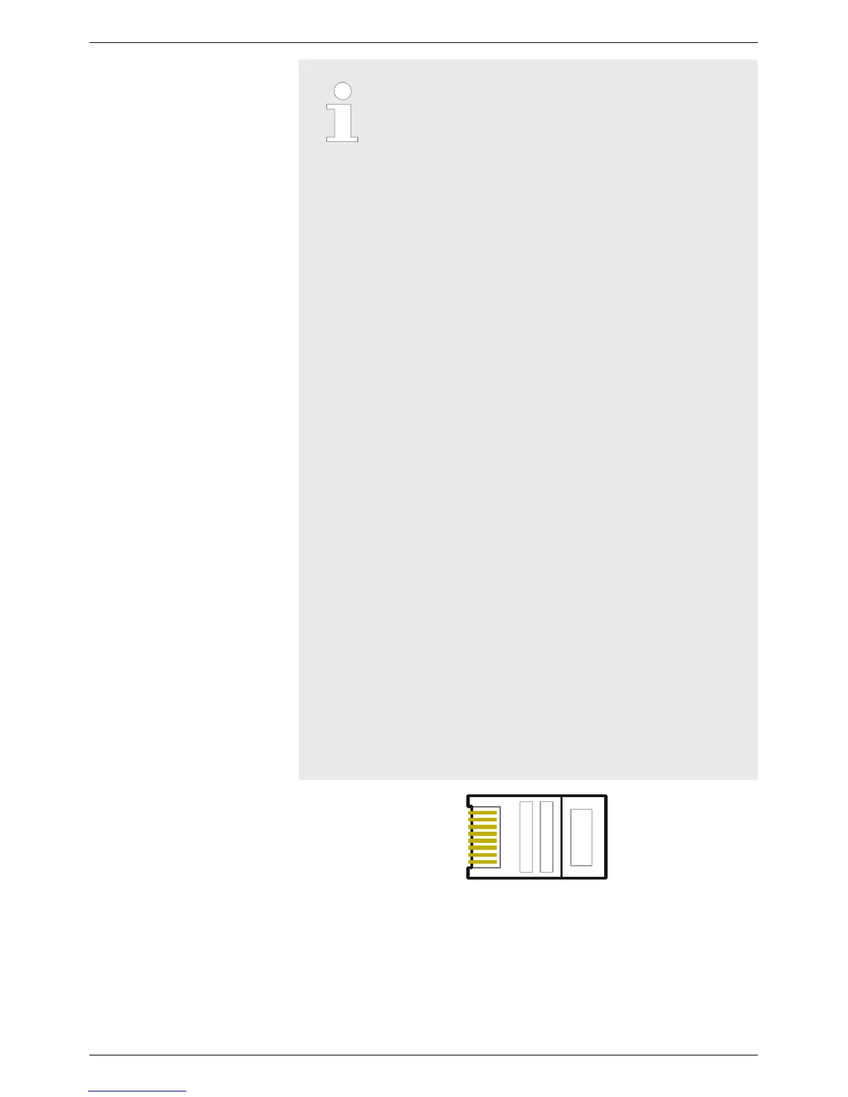
1)
Contact assignment of the RJ45 plug for the
RS485 bus: See Fig. 6.
2)
In this regard, see
⑥
under
Ä
Chapter 3.1.1
„coolcept
3
“ on page 11 and
⑦
and
⑨
under
Ä
Chapter 3.1.2 „coolcept
3
-x“ on page 12.
Fig. 6: Contact assignment (= line number) of the RJ45 plug
Optionally one (!) of the following masterdevices can be connected
to the RS485 bus. The devices support the transfer protocol used by
the inverter
. The devices support the transfer protocol used by the
inverter.
EN
750.661 | Z03 | 2016-09-12
25