NOTICE!
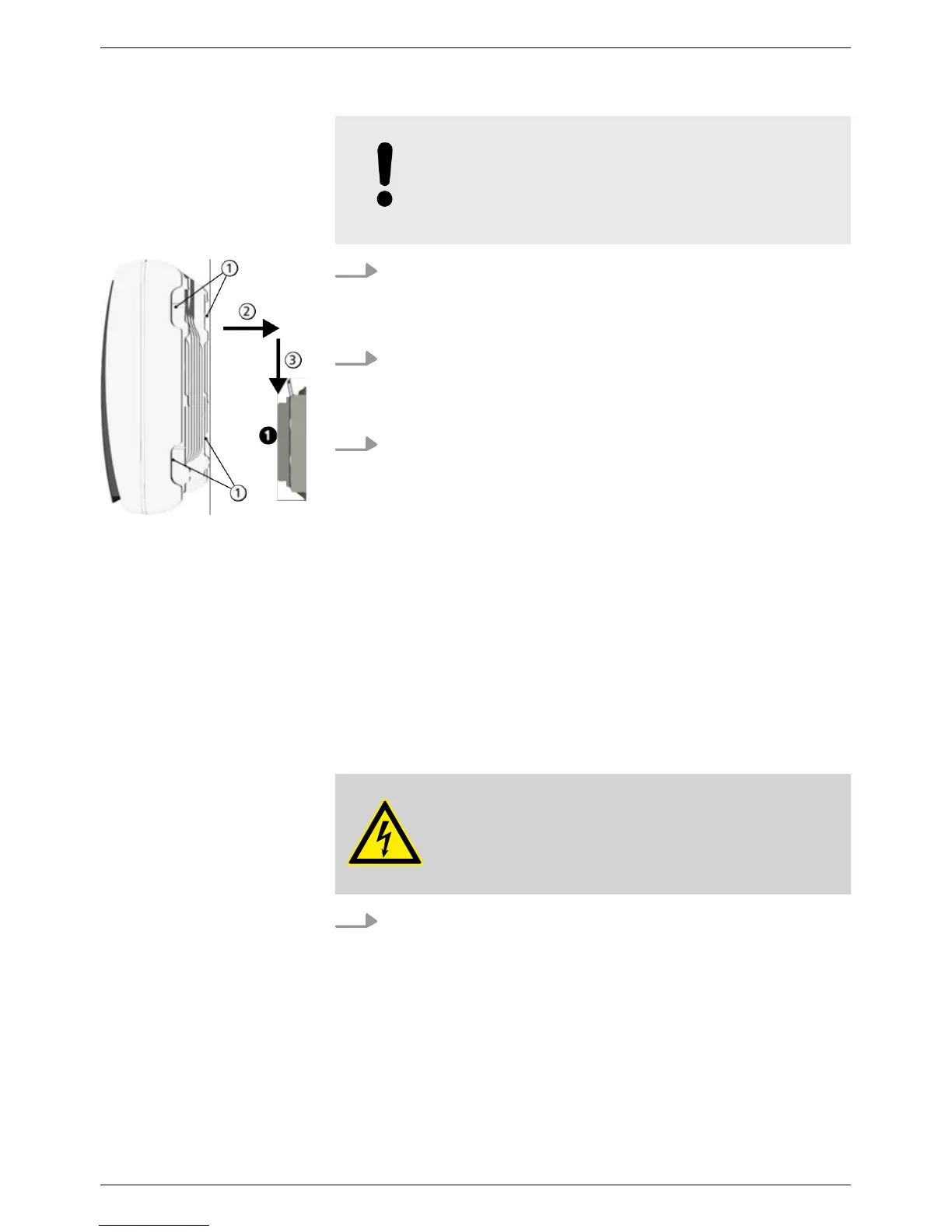
How to remove the inverter from the mounting
plate is described under
Ä
Chapter 4.9 „Switch
on DC“ on page 44.
1.
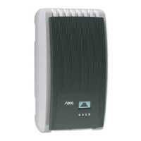
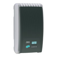
Grasp inverter on the grip recesses ①
(coolcept
3
) or by the
perimeter edge (coolcept
3
-x), fit it onto the mounting
plate ➊so that it is centred ② and lightly press it on (see the
example in the fig. on the left).
2. Lower the inverter ③ until the securing sheet metal element
of the mounting plate audibly locks in place. In this process,
the hooks on the rear of the inverter must be guided above
the catches on the mounting plate.
3. The inverter must now be firmly seated on the mounting
plate and it can no longer be lifted (upwards).
4.3
Prepare AC connection
4.3.1 Miniature circuit breaker
Information on the required line circuit breaker and the cables to be
used between the inverter and the line circuit breaker is provided in
Ä
Further information on page 69
4.3.2 Fault current circuit breaker
If the local installation regulations require the installation of an
external residual current circuit breaker, then a Type A residual cur-
rent circuit breaker as per IEC 62109-1, § 7.3.8. is sufficient.
4.3.3 Assemble AC plug
DANGER!
Risk of death by electrocution! Observe the
hazard warnings under !
Wire the AC plug supplied as shown in the figure below.
Attaching the inverter on
the mounting plate
EN
750.661 | Z03 | 2016-09-12
33