Shanghai STEP Electric Co., Ltd.
10
3.4.2 Definitions of control terminals
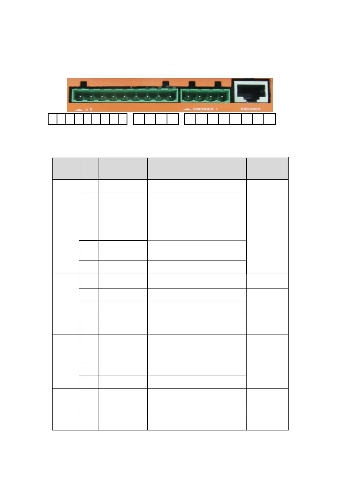
3.4.2.1 Definitions of control terminals of Type A1
1 2 3 4 5 6 7 8 9 10 11 12 13 14 15 16 17 18 19 20 21
Fig 3-6 sketch map of control terminals of Type A1
Specification of control terminals:
Table 3-2 Specification of control terminals of Type A1
Name
Numb
er
Function Instruction Signal level
Output
terminal
s
1 VCOM The jumper is 24V or 24V GND
24V,300mA
5 OUTPUT2
Fault closing signal output
terminal
Relay output
6
OUTPUT0 Signal output terminal of
door open limit
7
OUTPUT1 Signal output terminal of
door close limit
8
OUTPUT3
Fault signal output terminal
Input
termin
als
2 COM The jumper is 24VGND or 24V 24V,300mA
3 Open the door Openning signal input terminal
Optical
isolation input
4 Close the door Closing signal input terminal
9
Close the door
in ow speed
Closing in low speed signal
input terminal
Encoder
1
10 PA OCT , Push / Pull encoder PA
24V,300mA
11 PB OCT , Push / Pull encoder PB
12 +24V GND +24V GND
13 +24V +24V power supply
Encoder
2
15
+5V
+5V power supply
16 +5V GND +5V GND
17 A+ Differential encoder A+