Shanghai STEP Electric Co., Ltd.
14
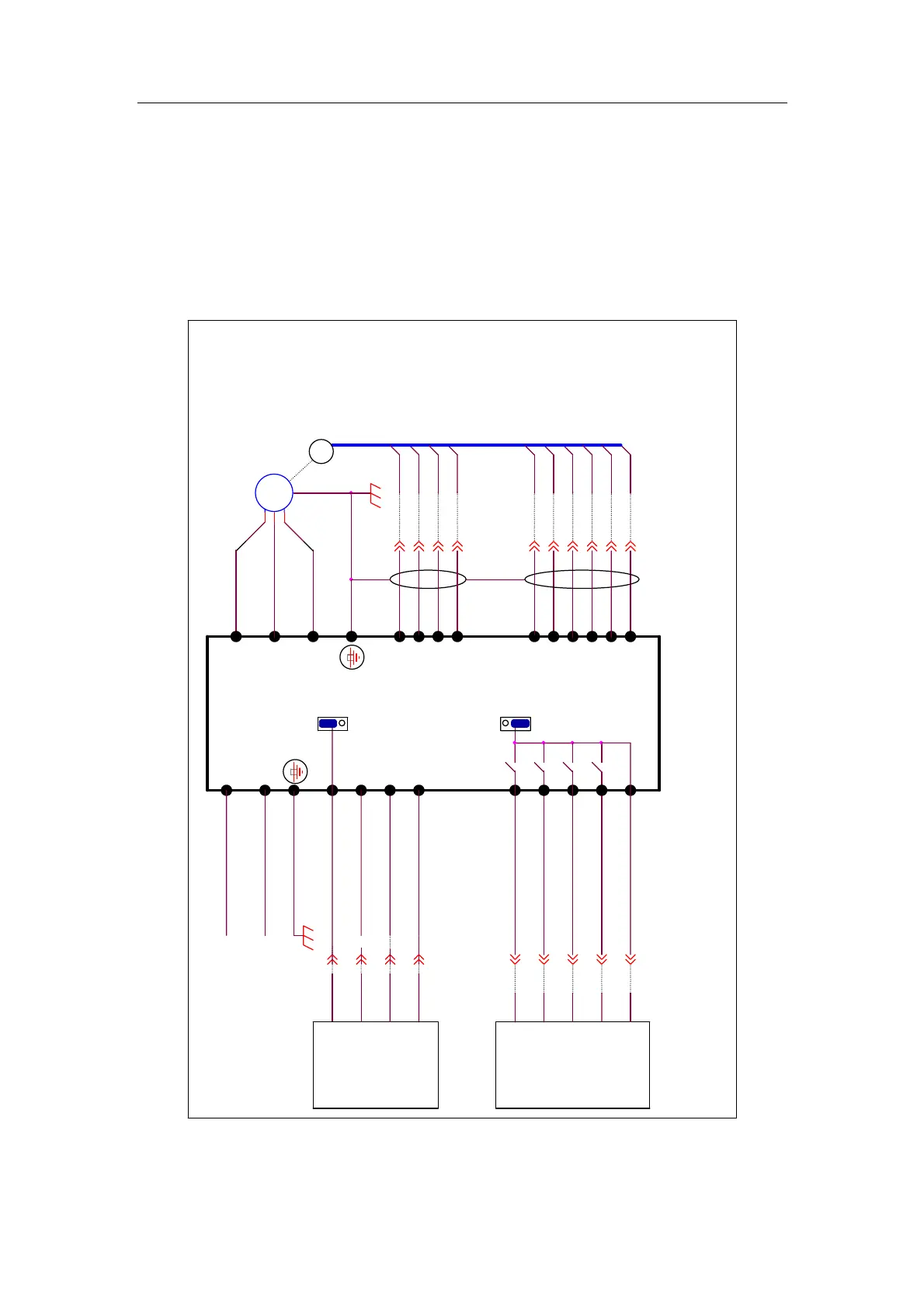
3.5 Basic diagram of inverter wiring
3.5.1 Basic diagram of inverter wiring for Type A1
3.5.1.1 Wiring diagram of main loop and control terminals for Type A1
M6
+5V
24V
9
1
N
S1
7
10
controller
door openning input signal
V
4
19
+24V
Type A1
4
G24
door closing in low
speed input signal
VCOM
2
door closing input signal
door openning to
position output signal
12
L
1
COM
2
elevator
24G
3
11
car board
PA
B-
6
A+
1
iAStar
GM
U
18
16
GND
pay special
attentions to
jumpers S1
and S2
3
Wiring of
encoder is shown
in the next
chapter
17
controller
G24
KM
or
door closing to position
output signal
single-phase power supply
AC220V 50/60Hz
M7
13
B+
1
PB
1
4
PG
NOTE:The 2 kinds of
encoders can not be used
in the same time
door machine
inverter
8
S2
11 1
fault output signal
A-
differential
type encoder
V6
5
9
elevator
24V
VCOM
Push/pull or
OCT output
encoder
M
~
3
2
15
20
1
3
W
door openning blocked
output signal
11
COM
9
1
CMM
Fig 3-8 Basic diagram of inverter wiring for type A1