STEP
iAStar Frequency Inverter For Elevator Door Machine manual Instructions
15
3.5.1.2 Wiring specifications of encoder
There are three kinds of encoder input signals for door inverter——encoder of
Push/pull, OCT or differential type. Please choose the encoder below 1024 pulse and
using 24V power supply.
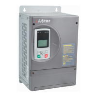
1) Push/pull or OCT output encoder wiring
VCC
GND
PA
PB
Push/Pull output encoder
iAStar inverter for door machine
Using shielded wires
Shielded wire connected to
19
20
21
22 +24V
+24VGND
PA
PB
OCT encoder
GND with close terminal
Fig 3-9 diagram of Push/pull or OCT output encoder wiring for Type A1
On the wiring of push/pull or OCT output encoder, the power of encoder should be
jointed at +24V terminal, the encoder ground at +24V GND terminal, PA and PB of
encoder at PA and PB of inverter, and the close terminal of shielded wire at GND
terminal of inverter. 。
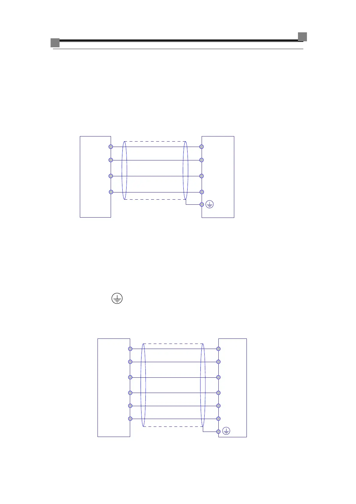
2) differential type encoder wiring
15
VCC
16
GND
17
18
20
19
Differential encoder
Using shielded wires
Shielded wire connected to GND with close terminal
+5V
GND
PA+
PB+
PA-
PB-
A+
B+
A-
B-
iAStar inverter for door machine
Fig 3-10 diagram of differential type encoder wiring for Type A1
 Loading...