STEP
iAStar Frequency Inverter For Elevator Door Machine manual Instructions
17
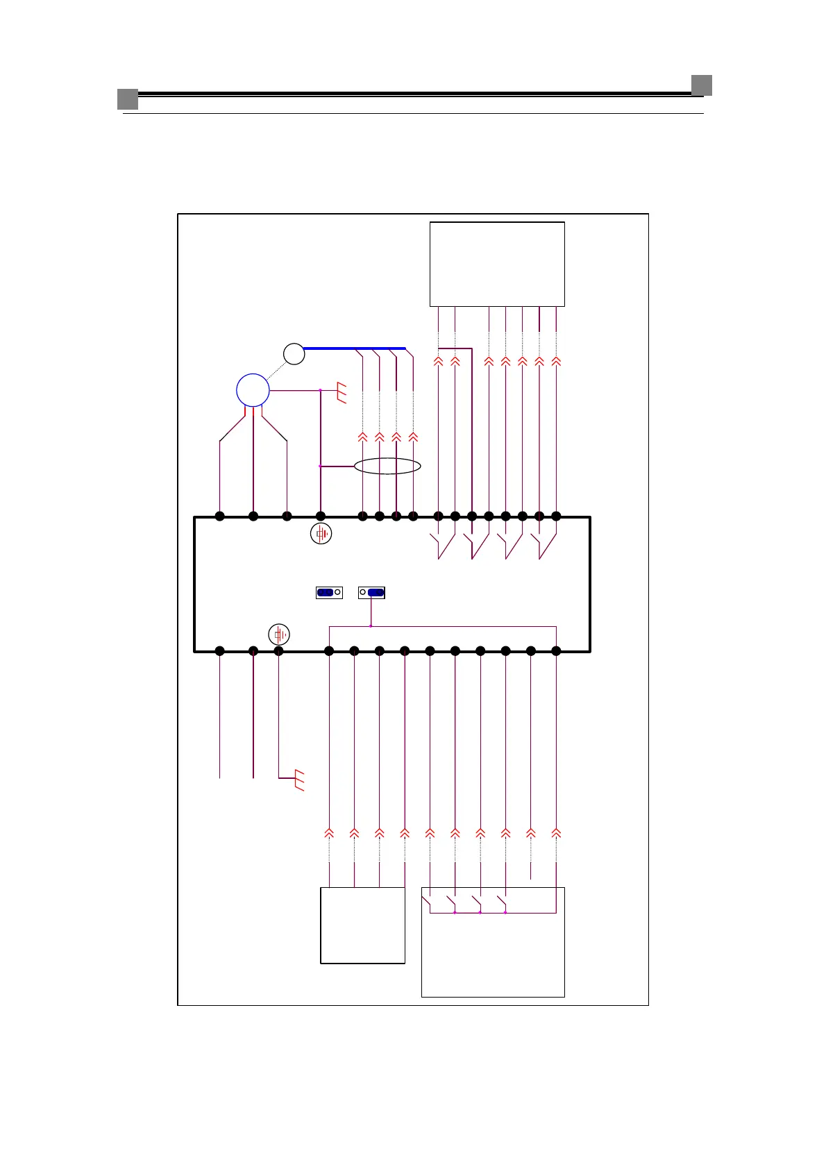
3.5.2 Basic diagram of inverter wiring for Type A2/A3
3.5.2.1 Wiring diagram of main loop and control terminals for Type A2/A3
spare input signal
single-phase
power supply
AC220V 50/60Hz
PB
7
6
17
elevator
3
Wiring of
encoder is shown
in the next
chapter
L
24G
2
K4
door openning to
position output signal
or
22 2
GM
2
door closing to position
input signal
1
4
KM
8
CMM
door closing to position
output signal
PG
door openning input signal
M
~
3
24V
iAStar
2
16
door closing in low
speed input signal
controller
door machine
inverter
1
11
1
9
COM
4
G24
19
VCOM
COM
2
S2
M7
14
W
door openning to
position input signal
decelerating closing
input signal
S1
K2
door openning blocked
output signal
controller
2
terminals
for
9
1
COM
2
Type A2
10
G24
2
car board
4
13
2
12
K1
1
24V
5
1
21
fault output signal
U
elevator
4 limit
Push/pull or
OCT output
encoder
+24V
COM
pay special
attentions to
jumpers S1
and S2
V
terninal
controlling
V6
K3
door closing input signal
2
M6
22
decelerating openning
input signal
N
9
18
K5
20
PA
3
15
图 3-12 Basic diagram of inverter wiring for type A2/A3