Shanghai STEP Electric Co., Ltd.
20
3.6 Wiring of jumpers
The input signal mode can be changed between common emitter mode (G24 is the
common point) and common collector mode (24V is the common point). Picture
shows as follows:
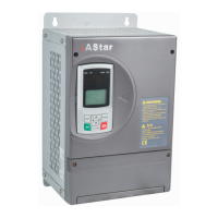
Fig 3-16 diagram of Wiring of S1、S2 jumpers(Type A1)
The functions of jumper S1 and S2 are described below:
Table 3-5 Specification of functions of jumper S1 and S2
name Terminal mark
S1 24V VCM G24
S2 24V COM G24
The power of digital input and relay output signal of the inverter is used interior 24V
power supply,and there are two types of setting jumpers according to the different
common level (high or low) of terminal COM, and the other ways setting jumpers will
lead to the abnormal operation of the circuit.
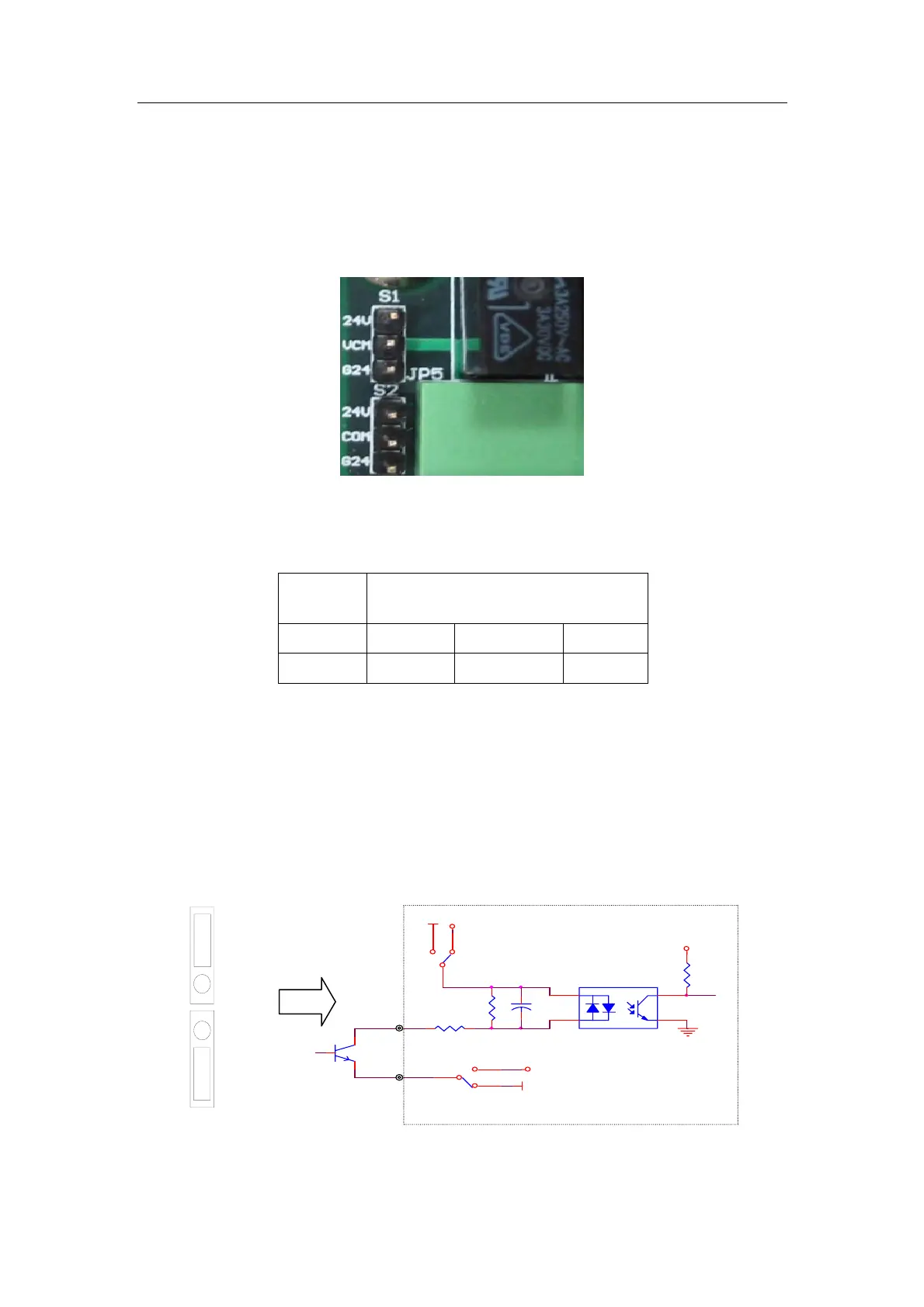
a) :Common emitter mode (G24 is the common point), common low level of
terminal COM, jumper S1 set to 24V-VCM, and jumper S2 set to COM- G24, the
position of the jumper and input schematic drawing shows below:
Fig 3-17 Common low-level input of terminal COM
24V
G24
VCM
24V
G24
COM
S1
VCM
G24
24V
S2
COM
G24
24V
G24
Set jumper S2 to COM-G24
VCC
24V
24V
Set jumper S1 to 24V-VCM
COM
DI1~DI3
1
2 3
G24