STEP
iAStar Frequency Inverter For Elevator Door Machine manual Instructions
21
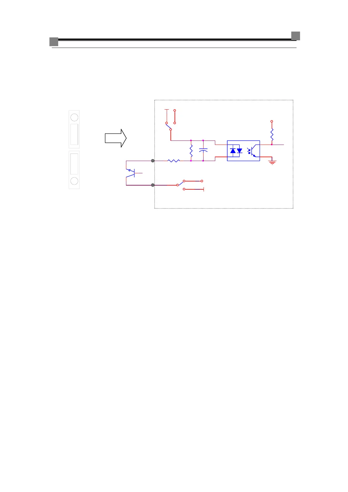
b) :Common collector mode (24V is the common point), common high level of
terminal COM, jumper S1 set to VCM- G24, and jumper S2 set to COM- 24V, the
position of the jumper and input schematic drawing shows below
Fig 3-18 Common high-level input of terminal COM
The power of digital input and relay output signal is used exterior 24V power
supply: jumper S1 and S2 don’t set, and connect 24V to terminal VCM and G24 to
terminal COM.
24V
G24
VCM
24V
G24
COM
G24
24V
S1
VCM
G24
24V
S2
COM
G24
24V
DI1~DI3
Set jumper S1 to VCM-G24
1
23
VCC
24VG24
Set jumper S2 to COM-24V
COM