STEP
iAStar Frequency Inverter For Elevator Door Machine manual Instructions
19
The 4 swiches ,door open limit swich,door close limit swich, Deceleration position of
openning swich and Deceleration position of closing swich, should be jointed at
terminal 13、14、15、16 ,and the other side should be jointed at terminal 18. and the
close terminal of shielded wire at GND terminal of inverter.
.
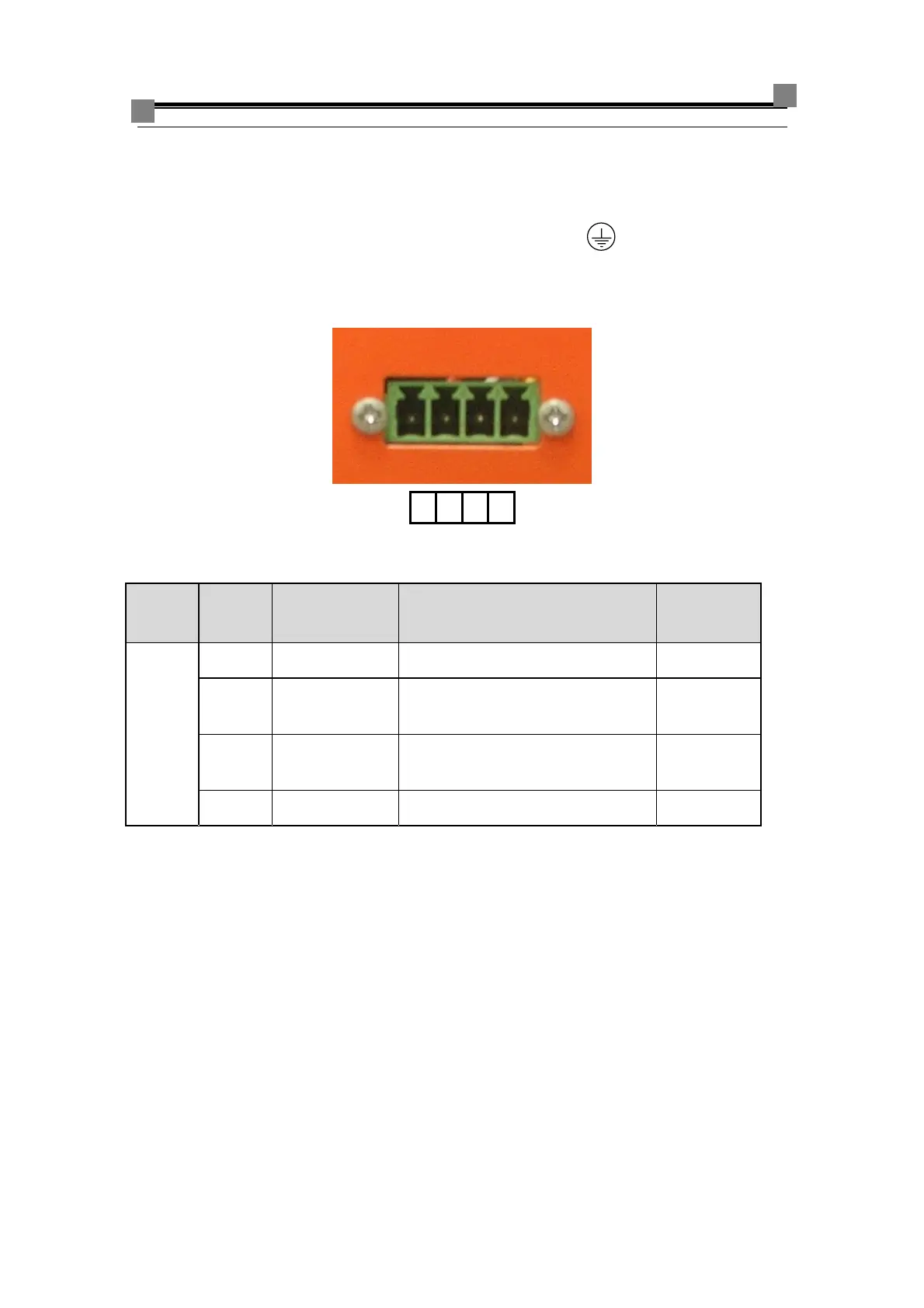
3.5.2.4 Description of connection of CAN communication
1234
Fig 3-15 diagram of connection of CAN communication for type A2/A3
Table 3-4 Specification of CAN BUS terminals
name
numbe
r
Function Instruction Signal level
CAN
Bus
1
GND
ground
2 CANH
High level of CAN BUS
input/output
3 CANL
low level of CAN BUS
input/output
4
spare
The socket of CAN communication is 4 pin. Corresponding wire is 4 bore.Connecting
methods see the diagram above.