Shanghai STEP Electric Co., Ltd.
16
On the wiring of differential encoder, the power of encoder should be jointed at +5V
terminal,the encoder ground at +5V GND terminal, A+, A-,B+, B- of encoder at
PA+、PA-、PB+、PB of inverter, and the close terminal of shielded wire at GND
terminal of inverter. 。
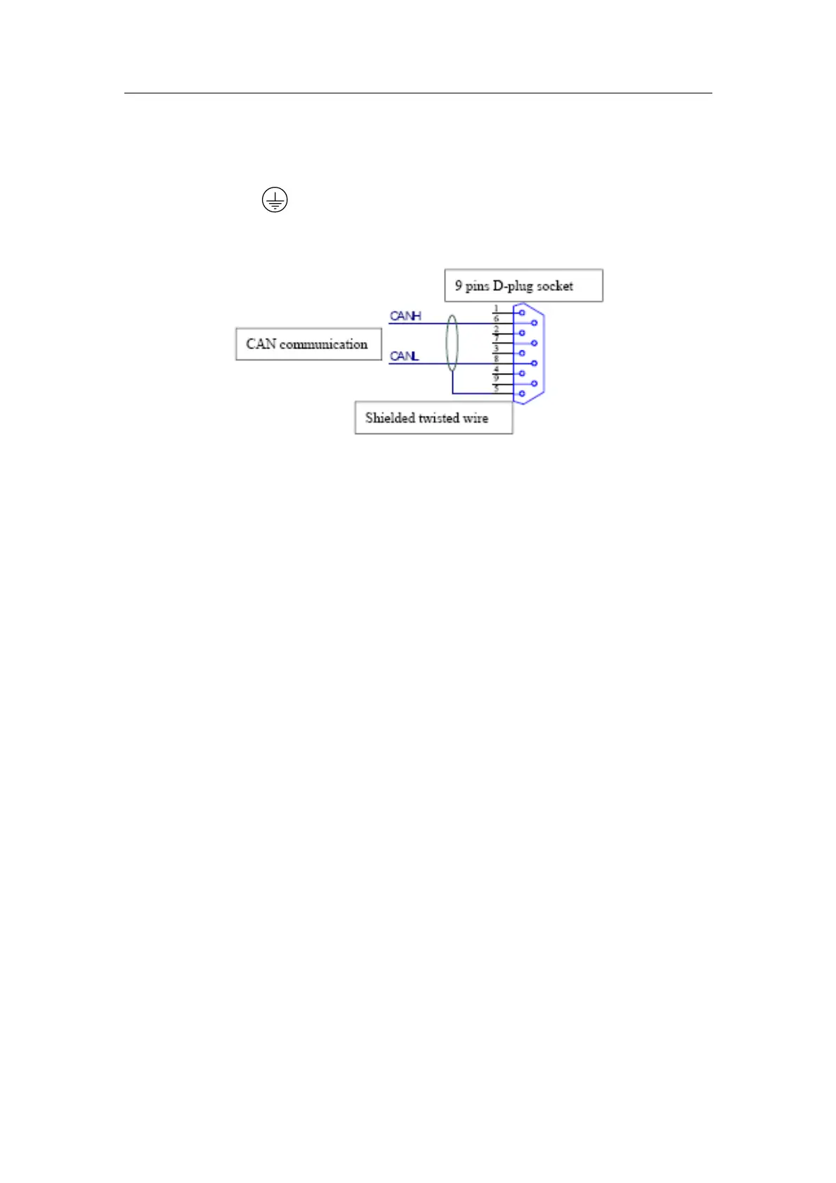
3.5.1.3 Description of connection of CAN communication
Fig 3-11 diagram of connection of CAN communication for type A1
The communication interface of CAN is at the right side of inverter. The socket is a D
type 9 pin. Corresponding wire is a D type 9 bore. Connecting method see the
diagram above.