12
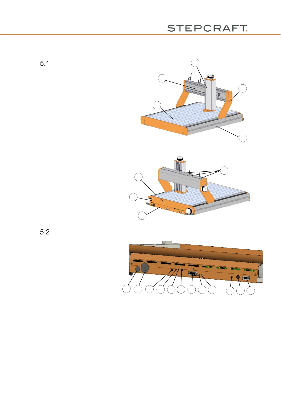
5. Drawings
Machine
1) Machine Table
2) Gantry
3) X-axis
4) Y-axis
5) Z-axis
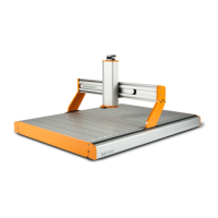
1) Flexi Guides
TM
2) Control electronics
3) Connection side
4) Vision panel status display UCCNC
and D-Series WinPC-NC module
Control
1) Passage air hose for ATC (optional)
2) Passage vacuum hose
3) Status display WinPC-NC module
4) Grounding cable
5) USB cable
6) Connection emergency switch
7) Connection external signals (see chapter 8.3.2)
8) Jack socket 1 (for example for connection tool length sensor or 3D touch probe)
9) Jack socket 2 (see 8)
10) Status displays control (see chapter 6.4)
11) Power supply connection
12) Connection 4
th
axis (only usable together with the optional motor driver board 4
th
axis)