17
Electrical Connection of the Machine
If you have purchased the machine as construction kit, the stepper motors as well as the reference
switch and the emergency stop switch have to be connected according to the assembly manual.
Connect the power supply with its low-voltage plug to the power connector socket at the rear side of
the machine. Due to reasons of reverse polarity protection, you have to connect the adapter plug with
the machine before connecting the power supply with the power socket as the machine has no sepa-
rate main switch. Make absolutely sure that the adapter plug is correctly aligned: The notch and the
flattened insulation have to be inserted facing upwards.
The computer has to be connected to the CNC system via parallel port, USB or network interface.
Please take the details regarding the respective connection from the control software you have
bought.
The LED lights of the control board (see chapter 5.2, position 10) are visible from outside. They flash
in case of:
LED2 red
System ok / Power amplifier switched on/ emergency-stop switched
off
Tools and Accessories
The machine features a 43 mm tool holder that can hold a variety of different tools. In addition to that,
the machine is extendable with supplementary system accessories.
Follow strictly the separate operating manuals of the used tools and accessories!
Below you will find a selection of available tools and system accessories for your CNC machine.
Please see our website (www.shop.stepcraft-systems.com
) for our complete range of products.
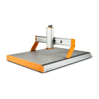
Milling Motor MM-800 11583
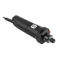
Milling Motor MM-1000 10022