EasyManua.ls Logo

STEPCRAFT M.1000 - Other Specifications; Pin Assignment Mainboard; Optional Modules; Connector Parallel Port

Default Icon
28 pages
Print Icon
To Next Page IconTo Next Page
To Previous Page IconTo Previous Page
Loading...
23
Other Specifications
M.500 M.700 M.1000
Passage height
135 / 205 mm
Repeatability
+/-0,025 mm (with opt. HIWIN® ball screws: +/-0,015 mm)
Programmable resolu-
tion
0,00625 mm
Backlash
< 0,05 mm (with opt. HIWIN® ball screws: < 0,03 mm)
Max. feed diagonal
travel X-Y
120 mm/s
Max. feed individual
axis
Up to 85 mm/s X-/ Y-axis, up to 50 mm/s Z-axis
Spindle (lead screw)
igus® dryspin 12 x 5 mm (opt. HIWIN® ball screws 12 x 5 mm)
Linear guide
Bosch Rexroth ball bearing guide
Drive
Stepper motors: Sanyo-Denki NEMA 23
Tool holder
Ø 43 mm (Euro neck, optional smaller diameters)
Weight
28,0 kg
35,0 kg
42,0 kg
Input voltage
100 240 V
Output voltage
24 30 V
Power consumption
180 W
Interface
USB / Parallel (LTP1) / Network RJ-45
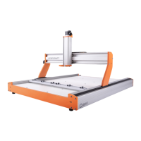
Pin Assignment Mainboard / Optional Modules
Connector Parallel Port
Signal Pin
Relay 1
1
DirX
2
Step X
3
DirY
4
Step Y
5
DirZ
6
Step Z
7
Dir 4
th
axis
8
Step 4
th
axis
9
Tool length sensor
10
Error
11
Reference switch X/Y/Z
12
Reference switch 4
th
axis
13
Relay 2
14
n.a. (in)
15
Relay 3
16
n.a. (out)
17
GND
18-25
PE
sched
5V VCC
1
14

Table of Contents

Other manuals for STEPCRAFT M.1000

Related product manuals