CLRS Series RS485 Closed Loop Stepper Drive User Manual
CL86RS
18-80VAC or 24-100VDC
no polarity
Note: When the user uses an AC transformer to supply power,
Be sure to use an isolation transformer to prevent electric shock or burn out the computer.
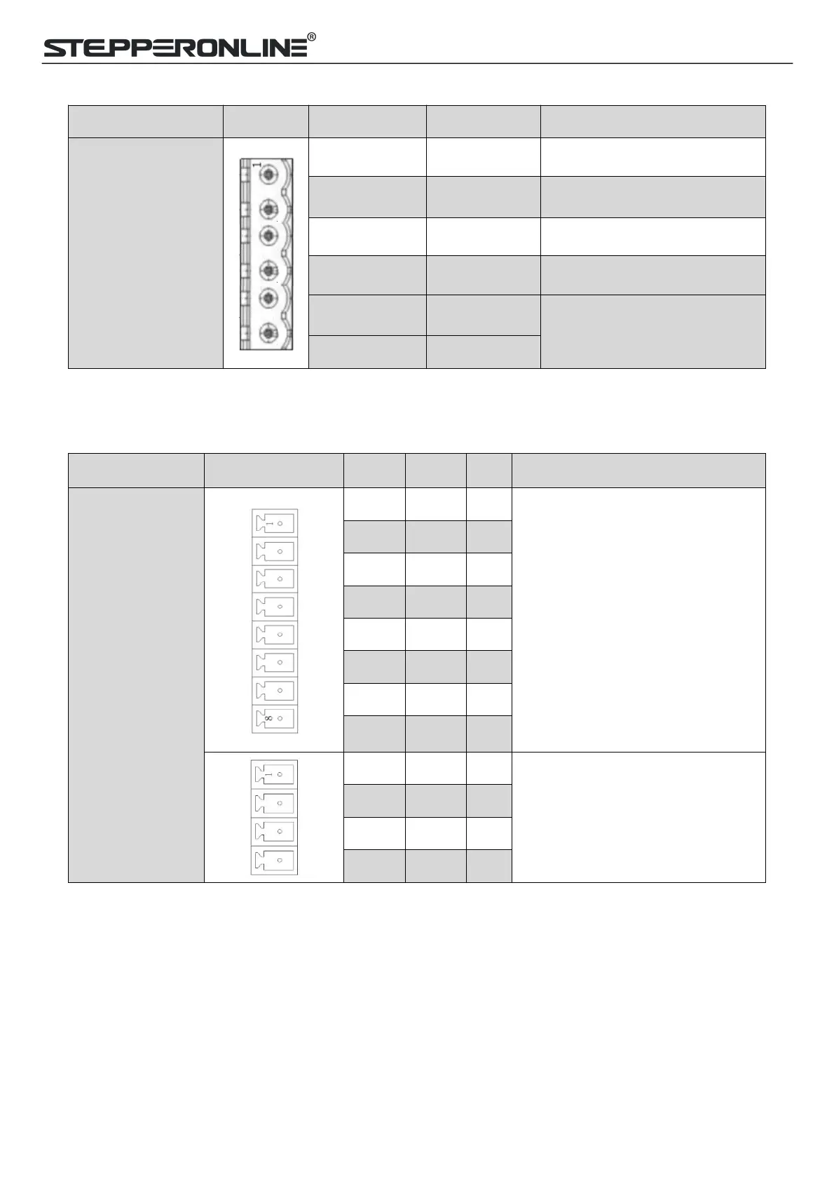
3.3.3 CN3-I/O Signals Connector
Configurable Single-ended Digital
Inputs DI1-DI7, 12V - 24V.
DI1 is enabling signal default, DI2-
DI7 are GPIOs.
Configurable Single-ended Outputs
Signals DO1-DO3 (common-
cathode or common-anode),
Max. 24V/100mA, GPIOs.
Note:(1) DI or DO is shown as SI or SO in STEPPERONLINE MotionStudio.
(2) DI1 is normally closed, default by Enable signal. It means the motor is locked shaft after the driver
powered on.
(3) When using brake output signals you need to connect a relay and a diode.

 Loading...


