4
Table of Illustrations
Initial Power-On Screen....................................................................................................... 9
Menu Screen ....................................................................................................................... 9
Screen After First-Time Power-On ..................................................................................... 11
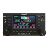
OptimizIR Front Panel ....................................................................................................... 12
Setup Main Menu .............................................................................................................. 14
Transceiver Interface to Radio........................................................................................... 19
Transceiver Interface with Y-cable ..................................................................................... 20
Controllers Stacked with Y-cable ....................................................................................... 21
Transceiver Interface to PC only ....................................................................................... 22
Screen Capture - AVR-Osp II ATxmega129A1 Programmer Panel .................................. 31
Tuning Relay Wiring .......................................................................................................... 32
Remote Driver Board Wiring .............................................................................................. 33
View of Memory Card Location ......................................................................................... 34
Front View of OptimizIR ..................................................................................................... 35
Rear View of OptimizIR ..................................................................................................... 35