Functional Description
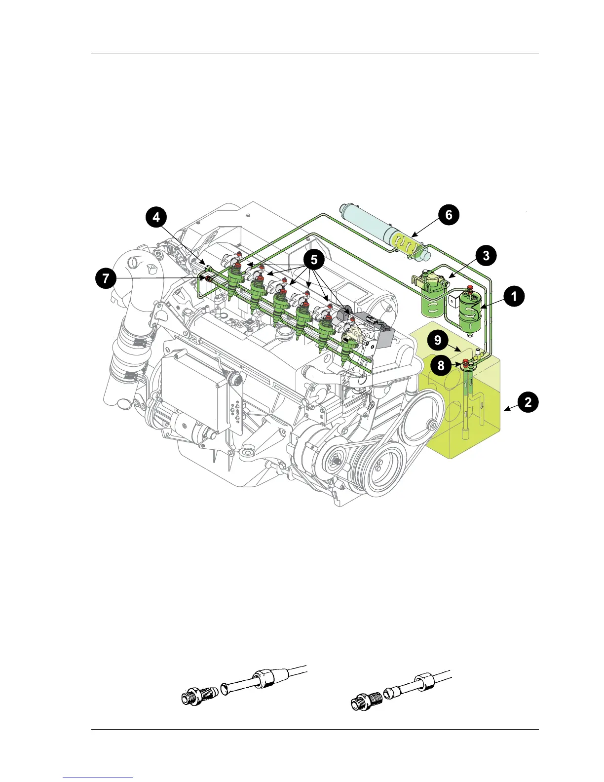
When the ignition switch is turned, an electric fuel pump 1 is put into operation and sucks fuel from
the fuel tank 2.Thisfuelisledviafuellter3 to the fuel pump. From the fuel pump, fuel is pumped
to the engine block 4 and the unit injectors 5. Excess fuel not injected by the unit injectors is led via
fuel cooler 6 back to the fuel tank.
The operating pressure is controlled by pressure valve 7 (1,8 - 2,5 bar at idle).
8 anti-siphon valve; 9bafes(dependingontanksize)
For fuel requirements, refer to chapter GENERAL
Specicationforfuelpipes
Minimum inside diameter: 8 mm
Recommended material: stainless steel or copper
NOTE: Min. inside diameter for hosepipes or PA-pipes is 10 mm.
Rateofow: > 240l/h +/-7 (in case of continuously operating pump)
Ifadditionalltersareinstalled,therequirementsof
higherowratesmusttobeconsidered.(lterdimension)
NOTE: In case of pipe connections, pay special attention to the
tightnessofthesuctionpipe(allttingsandlinebeforefuelpump)!
Types of pipe connections
03.00 ill. 2
03.00 ill. 1
 Loading...