Z001019/0_6_July 2008 Page ELECTRICAL SYSTEM - 85
ELECTRICAL SYSTEM
SERVICE MANUAL MARINE ENGINES
06.10.05 Check Sensors and Switches
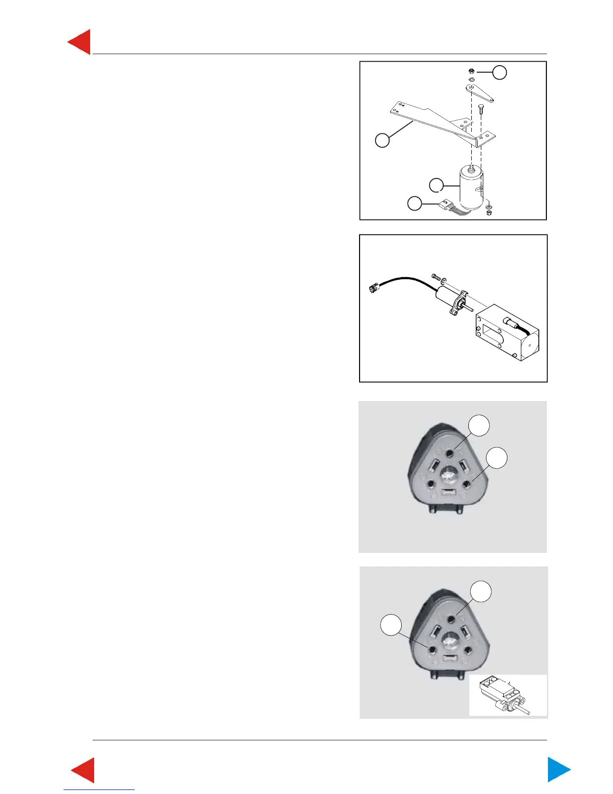
06.10.05.01 A Check rack position feedback sensor
B14 (= connector X14)
In case of defective rack position feedback sensor
B14, service codes (35) and (36) will flash.
NOTE: First always check cables and connections.
Final check:
Disassemble rack position feedback sensor
from control solenoid.
1 Check resistance between terminals A and C with a
digital ohmmeter. Resistance must be between
2,2 kOhm ± 10 %.
2 Measure resistance between terminals B and C with
extended shaft. Resistance must be
0,5 kOhm ± 10 %.
C
B
10.05 A ill.3
C
A
10.05 A ill.2
10.05 A ill.1
3
1
4
2
10.04 ill. 9
ToC
 Loading...