Z001019/0_6_July 2008 Page COOLING SYSTEM - 37
SERVICE MANUAL MARINE ENGINES
05 COOLING SYSTEM
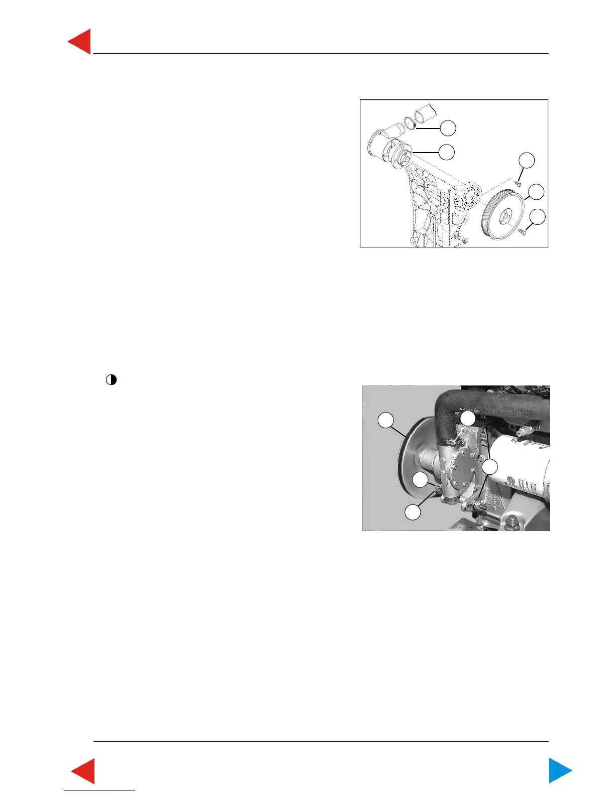
10.01 ill.1
1
2
3
4
5
10.01 ill.2
3
4
2
1
5
05.10 RAW WATER PUMP
05.10.01 Exchange raw water pump
1 Loosen 3 hexagon screws (ill.1/pos.1) of belt pulley.
2 Remove poly-V-belt or V-belt (05.06 or 05.07)
3 Unscrew 3 screws (ill.1/pos.1) of belt pulley and
remove belt pulley (ill.1/pos.2).
4 Loosen hose clamp (ill.1/pos.3) and remove hose.
5 Loosen 4 screws (ill.1/pos.4), remove raw water
pump (ill.1/pos.5).
6 Assembly is done in reverse order.
7 Torque screws M6 (pos.4) with 9,5 Nm; screws M8
(pos.1) with 23 Nm.
Secure all threads with LOCTITE 243.
For 6 cyl. engines only (old version)
1 Loosen two setscrews (SW17) (ill.2/pos.1)
2 Loosen hexagon nut of clamp bolt (ill.2/pos.2),
relieve V-belt by turning clamp bolt (ill.2/pos.3)
counterclockwise.
3 Remove V-belt (ill.2/pos.4).
4 Loosen hose clamps (ill.2/pos.5) and remove hoses.
5 Unscrew two setscrews (SW17) (ill.2/pos.1+2).
Remove raw water pump with tightener.
5 Loosen 4 hexagon screws (SW13), remove raw
water pump.
6 Assembly is done in reverse order.
ToC
 Loading...