03.08.03 Replace sensor, indication of control rack position
Preparation:
For 4 cyl. engines only
remove shift plate, refer to 01.08.01, ill.3.
For 6 cyl. engines only
remove bracket of potentiometer
accelerator, refer to 03.08.01, ill. 5-6
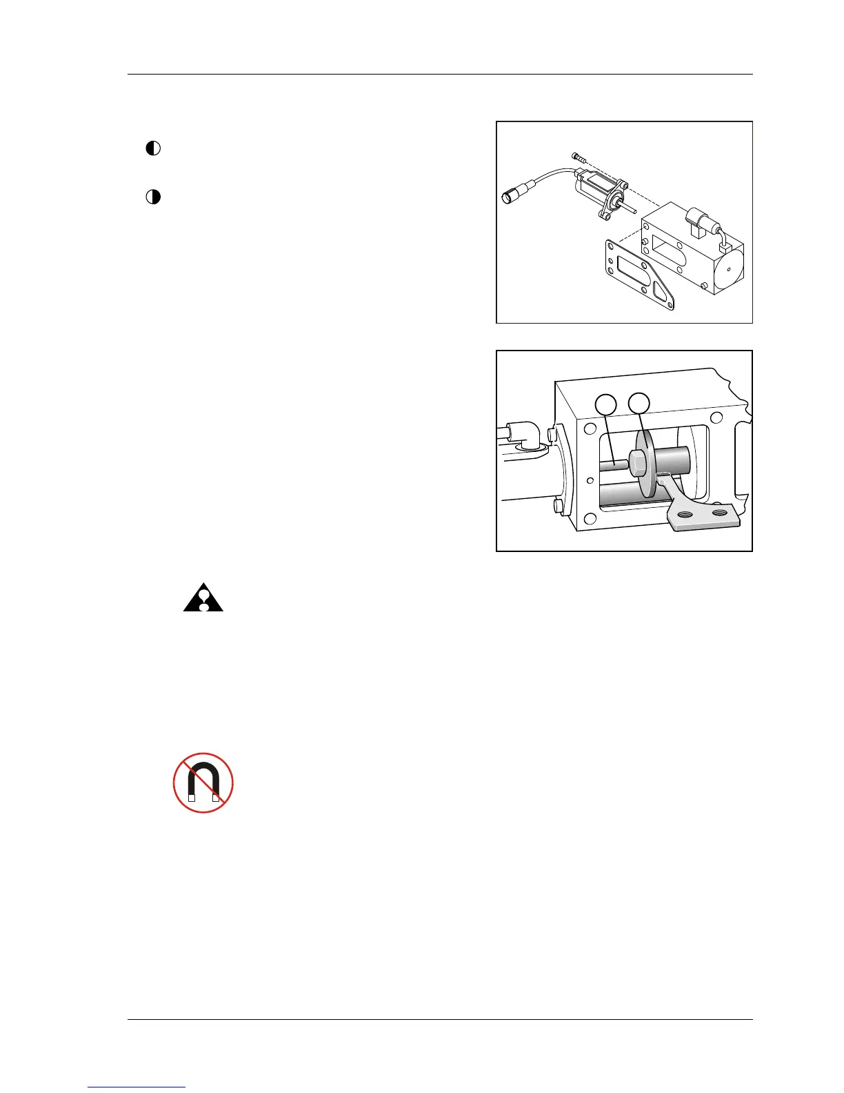
1 Loosen 2 Allen head screws (ill.1/pos.1) (SW3).
Remove rack position sensor.
Assembly
1 Insert new sensor in such a way that rod of poten-
tiometer (ill.2/pos.1) is positioned in front of solenoid
rod (ill.2/pos.2).
2 Secure 2 Allen head screws 3 mm with Loctite 243
and tighten with a torque of 5 Nm +/-0,5.
3 Check whether control rack can be moved over a
distance of approx.18mm.
ATTENTION: Rod of rack rack position sensor
is spring-loaded and might easily
slip off from the face of solenoid
rod (ill.2/pos.2), during assembly.
In such a case the control rack is
blocked, and thus prevents resetting
tozerodelivery
===> ENGINE FAILURE.
4 Remaining assembly is done in reverse oder.
NOTE: The rack position sensor is magnetism
sensitive. All external magnets must
be kept away as the may disturb the
sensor.
08.03 ill.1
08.03 ill.2
2
1
 Loading...