Z001019/0_6_July 2008 Page ELECTRICAL SYSTEM - 89
ELECTRICAL SYSTEM
SERVICE MANUAL MARINE ENGINES
06.10.05.04 Check speed sensor B15 and/or wiring
On account of the sensor's integrated electronic system, only the supply voltage and/or the output
signal and the continuity to control unit A5 can be measured.
Make sure that with disconnected plug X15 and ignition "ON" an error code can be stored
--> At completion of checking, cancel the error code; refer to 06.06.04
Use a standard voltmeter / multimeter to measure the supply voltage and/or the resistance.
Supply voltage Ubat (12V +/- 2V)
ignition ON main relay K27 active
measurement point GND on X15/3 against +supply voltage on X15/1
Continuity from X15/2 to control unit X5/33
max. resistance 2 ohms
If supply voltage and transition from X15/2 to X5/33 are connect, replace the speed sensor.
In case an error was detected during preceding measurements, check wiring according to circuit
diagram and wiring harness diagram.
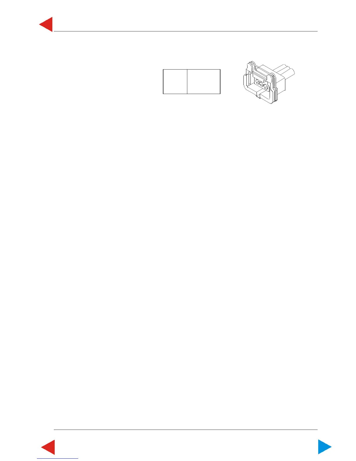
10.05 ill.9
X15
X 15/1 15012-06
X15/2 60113-01
X15/3 31000-03
1
2
3
ToC
 Loading...