ELECTRICAL SYSTEM
Page ELECTRICAL SYSTEM - 88 Z001019/0_6_July 2008
SERVICE MANUAL MARINE ENGINES
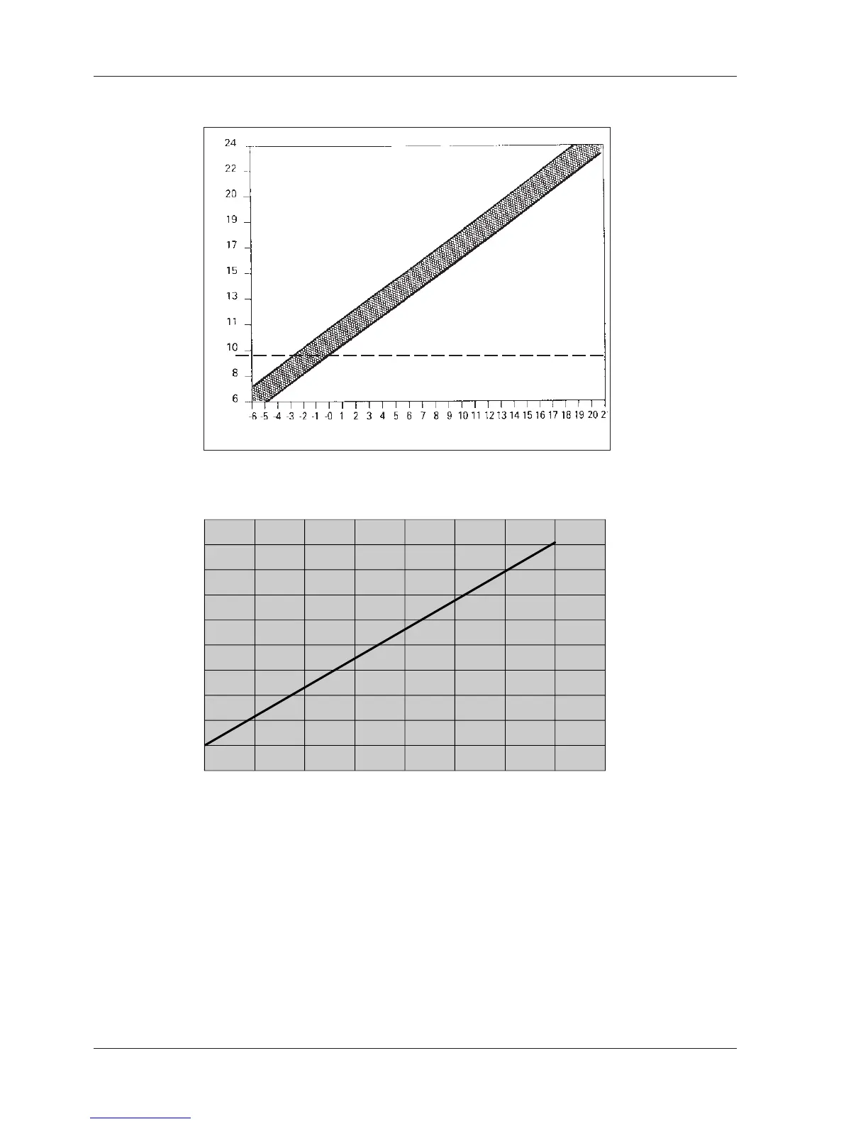
06.10.05.03 Check boost pressure sensor, B12, for engine models: 94 / 114 / 144 / 126 / 166 / 236
Athmospheric pressure
PSI
100 microbar (absolute)
10.05 ill.7
0,0
0,5
1,0
1,5
2,0
2,5
3,0
3,5
4,0
4,5
5,0
0,0 0,5 1,0 1,5 2,0 2,5 3,0 3,5 4,
Absolut - air pressure (bar)
Output - voltage (Volt)
Supply voltage
5V +/- 0,2V
Connector position
A = +5V
B = GND
C = Signal
Max. pressure with
3 bar (3,5 absolut)
10.05 ill.8
Pressure test:
For a pressure test of the sensor, disconnect the sensor hose and connect a pressure gauge with a
short piece of hose to the sensor.
Carefully pressurize the sensor. Read and record the values on the gauge (input pressure) and on the
display (output pressure) for 5 spots between 0 and 1.5 bar. Compare recorded input and output values
with the chart.
- If values are not within tolerance limits, replace the boost pressure sensor.
- If values are within tolerance limits, the boost pressure sensor is functional and the turbocharger
must be checked.
NOTE: Before checking the boost pressure sensor, check air filter, sensor hose and connector.
For engine models: 164 / 174 / 246 / 256 / 266
 Loading...