ELECTRICAL SYSTEM
Page ELECTRICAL SYSTEM - 86 Z001019/0_6_July 2008
SERVICE MANUAL MARINE ENGINES
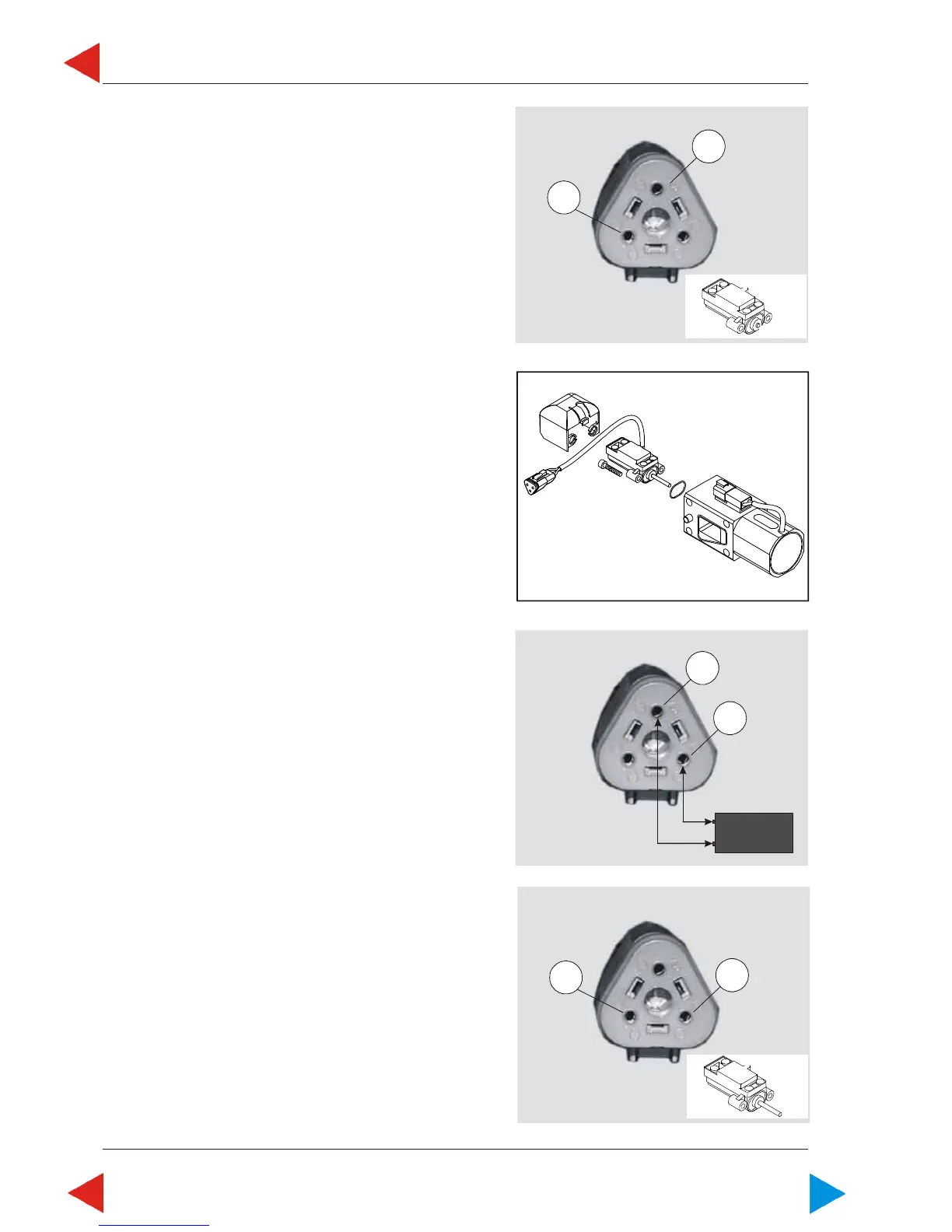
3 Measure resistance between
terminals B and C with inserted shaft.
Resistance must be
2,4 kOhm ± 10 %.
When a failure was found during one
of above checks, replace rack position
feedback sensor B14.
10.05 A ill.4
C
B
06.10.05.01 B Check rack position feedback sensor
B14 (= connector X14)
In case of defective rack position feedback sensor
B14, service codes 35 and 36 or 186 will flash.
NOTE: First always check cables and connections.
Final check:
Disassemble rack position feedback sensor
from control solenoid.
1 Supply terminals A ("-"; minus) and C ("+"; plus) with
5,0V DC +/- 1%.
2 Sensor extended!
Measure between terminal A (minus) and B (signal
out). Measured voltage must be 4,8V DC +/- 5%.
A
B
10.05 B ill.3
C
A
5V DC
+
-
10.05 B ill.2
10.05 B ill.1
ToC
 Loading...