Z001019/0_6_July 2008 Page COOLING SYSTEM - 25
SERVICE MANUAL MARINE ENGINES
05 COOLING SYSTEM
For 6 cyl. engines only (item 6-9)
Variant with gaskets:
6 Screw 3 assembly bolts for exhaust manifold No.
P/N V000229/0 into respective left tapped hole of
each seal. Put on new manifold seals.
7 Put exhaust manifold onto 3 assembly bolts (ill.5/
pos.1) Mount manifold screws with washers and
tighten sturdily. Remove assembly bolts and screw in
remaining 3 screws and 3 nuts with washers, and
tighten with a torque of 23 Nm +/-2.
Variant with O-rings:
8 Insert all O-rings into exhaust manifold by means of
Molykote.
9 Put exhaust manifold onto 3 assembly bolts (ill.5/
pos.1). Mount manifold screws and tighten sturdily.
Remove assembly bolts and screw in remaining 3
screw and 3 nuts. Tighten screws with a torque of
23 NM +/-2, nuts with 10 Nm.
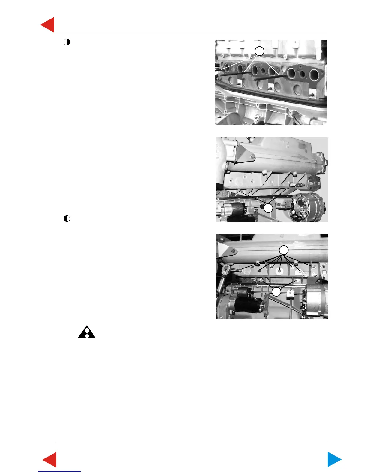
For 4 cyl. engines only (item 10-11)
10 Put exhaust manifold onto the two threaded bolts
(ill.6/pos.1).
11 Tighten 8 hexagon screws (SW13) (ill.7/pos.1) with
a torque of 23 Nm +/-2. Tighten 2 hexagon nuts
10 Nm (SW 10) (ill.7/pos.2).
12 Further assembly is done in reverse order of
disassembly.
ATTENTION: Plug and cable of speed sensor to
be tied up again with 2 cable ties on
venting hose.
13 Mount E-box properly.
14 Fill heat exchanger and motorblock with coolant,
according to instructions in this paragraph.
õ
01.05 ill.6
01.05 ill.7
1
2
1
01.05 ill.5
1
ToC
 Loading...